Nur noch wenige Schritte trennen uns davon den Motor in ein Testfahrzeug einzuhängen.

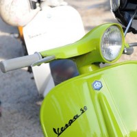
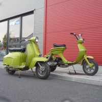
Als Testopfer für unseren Polini-Motor, greifen wir auf die bekannte Silver Fern zurück.
Bei der Polrad Montage darauf achten, dass man mit der Nut den Halbmondkeil genau trifft.

Anschließend wird die Polradmutter mit 65Nm angezogen. Unterlegscheibe nicht vergessen !

Die hintere Bremstrommel wird zunächst nur aufgesteckt und mit der Mutter fixiert.

Sobald die Hinterradbremse funktionstüchtig ist, kann die Bremstrommel mit 110Nm befestigt werden. Sicherungskäfig und Splint dürfen natürlich nicht fehlen.

Die Bedienelemente vom Lenker verbinden wir noch mit dem Motor, sprich Gas-, Schalt- und Kupplungszug werden befestigt und eingestellt.

Das Sicherheitsspiel am Kupplungshebel sollte zwischen 1,5mm und 2mm betragen, um zu vermeiden das bei Schaltvorgängen in höhere Gänge der Kupplungszug betätigt wird und somit der Druckpilz auf die Andruckplatte wirkt und die Kupplung eventuell sogar betätigt.

Öl und Benzinschlauch folgen. Die Luftblase im Ölschlauch ist gewollt. Beim ersten Anschliessen kann man so kontrollieren ob das Öl von der Pumpe in den Vergaser befördert wird.

Grösser als hier gezeigt sollte die Luftblase allerdings nicht sein, sonst besteht die Gefahr, dass die Pumpe leer läuft und kein Öl mehr in Richtung Vergaser transportiert wird.

Für das „first firing“ füllen wir 1Liter Super in einer Mischung von 1:50 in den Tank. Diese Treibstoffmenge sollte ausreichen um den Zeitrum zu überbrücken, bis die Ölpumpe den wertvollen Schmiersaft fördert.

Letze fehlenden Teile sind die Lüfterradabdeckung und die Zylinderhaube.

Dann heisst es Feuer Frei!

Nach ein paar Minuten warm laufen, schalten wir zunächst alle Gänge einmal durch und testen ob alle Gänge halten und die Kupplung sauber trennt.

Ein kurzer Blick auf den Öl-Schlauch verrät – Pumpe: läuft.

Also dann, erster Versuch auf dem Prüfstand mit folgendem Setup:

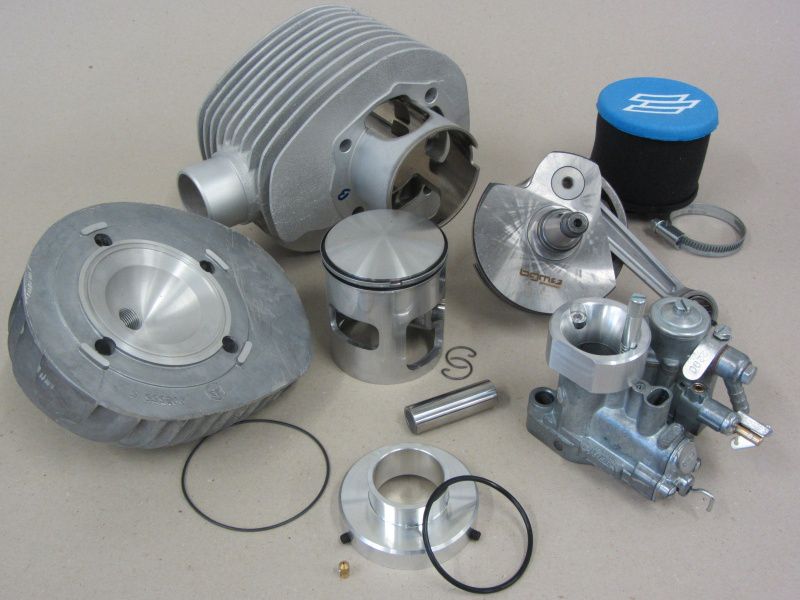
-Polini 210, Auslass, Kolben und Überstromkanäle sind nicht bearbeitet, Spacer Zylinderfuß 1mm.

SI 26, Cosa Schwimmerkammerdeckel mit Zusatzbohrung, Düsenstock ebenfalls mit Zusatzbohrung

-Bedüsung 48/160160BE3-ein Set Hauptdüsen zum herumspielen

-Einlassbereich von den störenden Kanten befreit, die Dichtungen entsprechend der neuen Kontur angepasst. Polini Ansaugtrichter mit Adapter und Polini Luftfilter.

bgm-Pro 60mm Kurbelwelle

Auspuff SIP Road

Zündung 18° v.Ot.

Zylinderkopf Worb5

Zur Sicherheit kontrollieren wir die Zündeinstellung per Umschlagsmessung. Wenn die Toleranzen an Kurbelwelle, Polrad und Grundplatte stimmen, sollte beim Anblitzen die Markierungen übereinander stehen. Dieses mal haben wir die 18° Markierung auf dem Polrad vorgenommen.

Ok, Zündung stimmt – dann steht dem ersten Testlauf nichts mehr im Weg…

Today we found the time to have a look at the port timings of the Polini kit.

With a 1mm base gasket one look at the degree disc shows us transfer port timings of 125° and exhaust timing of 172°. This results in a blow down timing of 23.5°.

Figures that really worth to try on the dyno and figures that should result in fast road engine with torque capable of raching high revs for good speed.

We have three different cylinder head designs to test on the engine. And this will be the first mod on the dyno.

We are going to try the MMW for 57mm stroke, the MMW for 60mmstroke as well as the Worb5 head for 57mm stroke.

On a first sight at the head we have a look at the squish clearance. The MMW 57mm version is a little bit tight at our 60mm crank. The squish would be 1mm on our setup, but well worth to try it with an additional head gasket. The MMW head for 60mm stroke is designed with a recess for the longer stroke. Used with our 1mm base gasket to achieve the right port timings we have a squish clearance of 2.7mm. So we have this head as an option if we want to try the setup without the base gasket. If we don’t use the base gasket anymore the port timings are lowered, but with the effect that the blow down timing is increasing. This is because of the greater reduction of transfer timing compared to the exhaust timing.

The Worb5 head is machined for the 57mm stroke, but with more squish clearance machined into the head. So we have a very useable squish clearance of 1.7mm without additional head gasket.

The different combustion chamber designs we will test on the dyno the next days. Can’t wait!

But the carb ist still waiting for fitment. And there are some important steps on the way to take care off.

First of all you have to be careful with the use of sealer. On self-lubrication Vespas the hole marked red in the picture feeds crankshaft, barrel and flywheel side bearing wih oil. If this is blocked no oil gets in and the trouble free miles will be very limited.

The very basic design of the SI carb range is very soli. But one to watch out for is the mounting of the carb, this can easily be destroyed.

If the nuts are over tightened the carb is warped and a sticking slide is the result of it.At least the later version of the SI carb is improved in this area and the nuts can’t bend the carb so that the slide sticks.

The pictures shows this feature on the later carbs and this recess can easily be done to later SI carbs.

But even on the later version the carb nuts shouldn’t be tightened not more than 16-18Nm. And they shouldnot be fully tightened from the start. Instead tighten they evenly and in turn.

For the carb mounting there are two different version available as well.

The „old“ version with studs and sleeve nuts are there untill the SI carb was used first. The new version was introduced with self lubrication P-ranges labelled EFL, Arcobaleno or Lusso.

The ida came up because this was easier to fit. Carbs without self-lubrication are fitted with a very long air adjuster screw and slide hook.

Before the carb is fitted into its box we cut a slot into the air adjuster screw this makes adjustment much easier on a later point.

Damn, we spoilt it!

That happens too often. So you have to take care that the hook hits the clip of the oil pump.

If the carb is fitted like the one pictured, it simply won’t work and you foul the slide hook.

Studs for carb fitment are not supporting good work flow and Piaggio introduced the sleeved screw. But this advantage brings a risk.

The screw next to the end of the scoots is located right above the rotary valve.

If you don’t use the right washer and spring washer the rotary valve surface will for sure be destroyed.

Tighten it down in steps of 8, 12, 16 Nm.

The Polini bellmouth is secured by only one screw. The idle adjustment screw can be used to get the location of the glory hole right. So simply adjust it that idle adjustment screw and the hole align.

For the dyno sessions we simply screw it to the carb. When all the jetting is done and we are happy with it, we glue the screw into place with threadlock.

The stator plate is adjusted to 18°. This equals to th „IT“ marking at the plate.

Jetzt geht es mit dem Messen der Steuerzeiten und den finalen Schritten vor den ersten Prüfstandsläufen los.

Mit einer 1mm Zylinderfußdichtung verrät uns die Gradscheibe einen Überstromwinkel von 125° und einen Auslasswinkel von 172°.

Werte mit denen man auf jeden Fall einaml ein paar Versuche fahren sollte.

3 verschiedene Zylinderköpfe probieren wir direkt auch noch aus.

MMW für 57mm und 60mm Hub und einen Wrob 5 Zylinderkopf für 57mm Hub.

Zunächst betrachten wir nur das Quetschmaß. Der MMW-Kopf für 57mm Hub fällt erwartungsgemäß mit 1,0mm etwas knapp aus, einen Test mit einer zusätzlichen Zylinderkopfdichtung von 0,5mm oder 0,8mm kommt dennoch in Frage. Der Kopf für 60mm Hub ist praktisch als Kopfdichtungsvariante ausgeführt und gleicht den Hubunterschied von 1,5mm durch den Brennraum aus, daher fällt hier das Quetschmaß mit 2,7mm erwartungsgemäß recht hoch aus.

Allerdings lässt der MMW Zylinderkopf für 60mm Hub dadurch auch den Spielraum den Zylinder wieder tiefer zu setzen. Dadruch verkürzen sich zwar alle Steuerwinkel, jedoch ergibt sich daraus mehr Vorauslass, der sich vielleicht positiv auf das Fahrverhalten auswirken könnte.

Der Zylinderkopf von Worb5 wurde ebenfalls für 57mm Hub gefertigt, bekannter Weise ist das Quetschmaß auf 57mm Hub mit diesem Kopf recht groß. In unserem Fall ergibt sich dadurch bei 60mm Hub ein recht brauchbares Quetschmaß von 1,7mm ohne zusätzliche Zylinderkopfdichtung.

Inwieweit sich dann die verschiedenen Brennraumgeometrien auf die Leistungsentfaltung auswirken, werden wir auf unsserem Prüfstand ermitteln.

Auch die Montage vom Vergaser gehört zum Komplettieren des Motors.

Augenscheinlich ein recht triviales Thema, aber auch hier kann man gekonnt daneben schrauben.

Freunde der großzügigen Verwendung von Dichtmasse, sollten Vorsicht walten lassen. Der Kanal auf der Unterseite der Vergaserwanne und die Ölbohrung im Vergaser (hier rot markiert) müssen bei Motoren mit Getrenntschmierung unbedingt frei bleiben. Sind die Versorgungswege verschlossen, laufen Kurbelwelle, Lichtmaschinenlager und Zylinder ohne Öl; und das meist nicht lang‘.

Der genügsame SI-Vergaser an sich, reagiert sehr empfindlich auf eine falsche Befestigung.

Wer es beim anziehen der Schrauben übertreibt, könnte später mit einem klemmendem Schieber zu kämpfen haben. Alle neueren SI-Vergaser haben bereits eine Verbesserung erfahren, damit der Schraubenkopf nicht mehr unmittelbar auf die Schieberführung wirken kann.

Zu erkennen an einem kleinen Freistich. Diese Kniff lässt sich auch auf die älteren Vergaser übertragen.

Aber auch trotz dieser preventiven Maßnahme sollte man sich an den Drehmoment von 16-18Nm beim wechselseitigen Anziehen der Schrauben halten.

Bei der Vergaserbefestigung gibt es 2 Varianten die Verwendet werden können.

Die „alte“ Ausführung mit Stehbolzen und Hülsenmuttern gibt es, seit Largeframes mit SI Vergaser gibt ausgerüstet wurden. Die neuere Variante mit einer Schaftschraube kam erst mit den Lusso oder besser den Modellen mit Getrenntschmierung auf.

Hintergrund dafür ist einfach die Montagefreundlichkeit. Vergaser mit Getrenntschmierung sind aufgrund der besseren Zugänglichkeit, mit einer auffällig langen Gemischeinstellschraube und einer Schieberstange zum einhaken bestückt. Zur verwendung auf Motoren mit Gemischschmierung kann die Zugstange auch einfach ausgetauscht werden. Bevor der Vergaser in seiner Wanne Stellung bezieht, schlitzen wir mit einer Feile noch die Gemischeinstellschraube. Das erleichtert später das Einstellen.

Mist, daneben…

Das passiert gerne und oft.

Beim Einsetzen des Vergasers darauf achten dass der Haken die Lasche der Ölpumpe fängt.

Wird der Vergaser wie unten auf dem Bild festgeschraubt, beschädigt man zum einen die Schieberstange und zum anderen hätte man erfolgreich dafür gesorgt, den Vergaser ausser Funktion zu setzen.

Stehbolzen zur Vergaserbefestigung wären hier also hinderlich beim einsetzen, daher kam Piaggio auf die Idee mit den Schaftschrauben. Leider birgt die Vereinfachung ein kleines Risiko.

Die in Fahrtrichtung hintere Schraube, sitzt direkt über der Drehschieberfläche.

Wird an dieser Stelle vergessen die benötigte Scheibe oder Sprengring zu verwenden, kommt es unumgänglich zur Beschädigung des Drehschiebers.

In Schritten mit 8, 12, 16Nm wird der Vergaser befestigt.

Der Polini-Trichter wird lediglich mit einer Schraube fixirt. Die Leerlaufdrehzahlschraube dient nur zur Einbauorientierung, da der Trichter an dieser Stelle über eine Durchgangsbohrung verfügt.

Für den Prüfstand begnügen wir uns aufgrund der zu erwartenden Düsenwechel mit dem einfachen befestigen der einzigen Schraube. Sobald allerdings eine passende Vergasereinstellung gefunden ist,
sollte man die Schraube mit Schraubensicherung fixiren.

Die Zündgrundplatte stellen wir für die ersten Testläufe auf die „IT“ Markierung, also einen Zündzeitpunkt von 18° v.Ot ein.


DRIVE

AbenteuerHallenKALK
Christian-Sünner-Straße 8
51103 Köln

Germany

Tel. +49 (0)2 21. 8 80 84 08
www.abenteuer-halle.de

> Parking near the venue.

[googleMap name=“AbenteuerHallen KALK“ description=“AbenteuerHallen KALK“ width=“600″ height=“600″]Christian-Sünner-Straße 8 51103 Köln[/googleMap]


ANFAHRT

AbenteuerHallenKALK
Christian-Sünner-Straße 8
51103 Köln

Tel. 02 21. 8 80 84 08
www.abenteuer-halle.de

Anreise mit dem Auto:
> A3/A4 Abfahrt „Kreuz Köln-Ost“
> B55a Richtung Köln Messe
> Abfahrt „Buchheim“
> links abbiegen auf B8
> rechts ab auf B55 („Kalker Hauptstr.“)
> links abbiegen („Kapellenstr.“)
> Kreisverkehr 2. Ausfahrt („Dillenburger Str.“)
> erste rechts abbiegen („Christian-Sünner-Str.“)
> Parkplätze sind vor Ort.

[googleMap name=“AbenteuerHallen KALK“ description=“AbenteuerHallen KALK“ width=“600″ height=“600″]Christian-Sünner-Straße 8 51103 Köln[/googleMap]

Anreise mit öffentlichen Verkehrsmitteln:
> Ab Bahnhof Köln-Deutz mit Linie 9 Ri. Königsforst
oder Linie 1 Ri. Refrath oder Bensberg
bis U-Bahn-Haltestelle „Kalk Kapelle“
>von dort in die „Wiersbergstraße“
>immer geradeaus bis Schlagbaum
>kleines Fußgängertor passieren
>auf der rechten Seite liegen die AbenteuerHallenKALK.
>Die S-Bahn Haltestelle „Trimbornstraße“ (S12)
liegt 500 m entfernt.

Jugendherberge Köln-Deutz
Siegesstr. 5 · 50679 Köln
Tel.: +49 (0)221-814711
Fax: +49 (0)221-884425
Mail: koeln-deutz@jugendherberge.de

There will be a trophy for every first and second position in the custom classes listed below –
each for Automatic and Classic :

  • BEST OF ALL
  • BEST RACER – Fullframe race scoot
  • BEST SPRINTER – Best 1/8 or 1/4 Mile racers
  • BEST BODYWORK – best modified bodywork
  • BEST CUSTOM – beste Customizing
  • BEST STREETCUSTOM – best Custom scoot used on the road
  • BEST PAINT – best paint, best Airbrush or best original paint
  • BEST PLATING – bes chrome, gold plating and/or engraving
  • BEST DISPLAY – best display
  • BEST ODDITY – stangest idea on show


Pokale gibt es für den ersten und zweiten Platz in den folgenden Custom Klassen –
jeweils für Automatik und Klassik :

  • BEST OF ALL
  • BEST RACER – Fullframe Rennroller
  • BEST SPRINTER – Beste 1/8 oder 1/4 Mile Geschoße
  • BEST BODYWORK – bester Karosserieumbau
  • BEST CUSTOM – beste Veredelung
  • BEST STREETCUSTOM – beste Veredelung im Alltagsgebrauch
  • BEST PAINT – beste Lackierung, bester Airbrush, bester Originallack
  • BEST PLATING – bester Roller mit Chrom, Gold und/oder Gravuren
  • BEST DISPLAY – beste Präsentation
  • BEST ODDITY – seltsamster Umbau

Infos zur Bewertung: In allen Klassen gibt es einen ersten und zweiten Platz. Automatik und Klassik Roller werden gesondert bewertet. Veranstalter Fahrzeuge sind von der Bewertung ausgeschlossen.

With appearance of the Polini Evolution cylinder kits at the scene, the cast iron barrels got updated as well. From then on the Polini cast iron barrel is labeled as Polini 133cc Racing. The most innovative feature is the new Polini 133 Racing cylinder head. A massive head with enlarged cooling fin area, CNC machined combustion chamber and copper head gasket.

Thank to the massive (anti-warp) thickness and the new head gasket design leaking heads are an issue of the past. At least if the head nuts are tigthened down properly.

The head is offered by Polini as an upgrade for all Polini 133cc kits as well. We will have a closer look if it is worth it. Longer cylinder studs are already included into the delivery of the head. Our recommended head nuts are those from Naraku.

The better cooling efficiency of the head gives room for a higher compression ratio.

With a burette we check the combustion chamber volume.

Compared to the old head with it’s 16.8ccm, the new head has 15.99ccm. This gives a higher compression ratio of 9.1:1 instead of the old 8,7:1.

The head gasket volume we have considered too. We used grease to simulate this.

The slightly higher compression ratio combined with the new combustion chamber area gives higher horsepower as well as torque readings. The better thermal absorption of the head gives the same reliabilty as on the lower compression head. At least if carb and ignition settings are properly done.

Once you have taken of the barrel, head or replaced any cylinder head or base gasket, you should always check the squish clearance of the top end. Depending on the specific engine setup. it might be a good idea to adjust the ignition timing too. With higher compression ratios it might be a good idea to reduce the ignition timing (=use a firing point closer to TDC).

The new Polini head is a nice and up to date improvement for the Polini 133cc kits. A good idea for all Class 5 racers at the ESC.

Mit dem Erscheinen der neuen Polini Evolution Zylinder hat der altbekannte Polini Grauguß Zylinder ebenfalls ein Upgrade erhalten und hat ab jetzt den Zusatz „Racing“ in der Bezeichnung. Einen wirklich massiven Zylinderkopf mit vergrößerter Kühlfläche, CNC bearbeitetem Brennraum und einer Kupferdichtung.

Durch die stark erhöhte Materialstärke und der Verwendung einer Kopfdichtung wie bei den Evolution Zylindern, gehören Undichtigkeiten am Zylinderkopf -richtige Montage vorausgesetzt- von nun an der Vergangenheit an.

Glücklicherweise bietet Polini den neuen Racing Zylinderkopf auch als Ersatzteil an, der auf jeden „alten“ Polini Adaptiert werden kann. Die zur Montage benötigten längeren Zylinderstehbolzen um den stärkeren Zylinderkopf zu befestigen, sind neben einer Zylinderkopfdichtung, im Lieferumfang enthalten. Zur Verschraubung empfehlen wir diese M7 Muttern von Naraku.

Durch die erhöhte Kühlleistung hat Polini dem neuen Racing Zylinderkopf auch etwas mehr Verdichtung zugestanden.

Mit einer Bürette haben wir für Euch einmal den Unterschied gemessen.

Im Vergleich zu seinem Vorgänger mit 16,8ccm Brennraumvolumen, kommt der neue Zylinderkopf mit einem Brennraumvolumen von 15,9ccm und erhöht somit die geometrische Verdichtung von 8,7:1 auf 9,1:1.

Das Volumen der Zylinderkopfdichtung haben wir beim Auslitern mit Fett simuliert.

Die dezent erhöhte Verdichtung, gepaart mit der moderneren Brennraumform, verhelfen dem Grauguß Polini zu mehr Drehmoment und Leistung, ohne dass es am Zylinderkopf zur thermischen Überanspruchung kommen kann. Das gilt selbstverständlich auch nur dann, wenn der Motor richtig eingestellt ist. Eine falsche Vergaser- und Zündeinstellung bügelt der neue Zylinderkopf natürlich nicht aus.

Zur Sicherheit solltet Ihr nach der Montage, das Quetschmaß neu ermitteln und je nach Motorsetup den Zündzeitpunkt anpassen. Mit erhöhter Verdichtung kann es unter Umständen nötig sein, den Zündzeitpunkt etwas später (also weniger Grad vor OT) zu wählen.

Der neue Polini Zylinderkopf ist auch für die Klasse 5 der ESC interessant, da er seit 2012 in Klasse 5a zugelassen ist.

The AbenteuerHallen KALK are located in Cologne’s eastend. The industrial appeal is perfectly suited for our Scootershow. It has 1.000 m² and celing height is 11m.
Scootershow 2013 Abenteuerhallen Kalk KölnHave a look at the pictures and imagie this space filled up with the best custom scoots.

Scootershow 2013 Abenteuerhallen Kalk KölnHere you see the catering that is available direct in the venue. Served are drinks and snacks. In waliking distance you will find a high street with all sorts of shopping facilities. From Kebap houses to the other wide spread fast food things.

Scootershow 2013 Abenteuerhallen Kalk Köln

A virtual walk around and all the info about the venue, you will find here: www.abenteuer-halle.de

Die AbenteuerHallen KALK im Kölner Osten bestehen aus einer umgebauten 1.000 qm großen und 11 m hohen ehemaligen Industriehalle.
Scootershow 2013 Abenteuerhallen Kalk KölnDer dort integerierte 1.000 qm großen „bike & skatepark“ bietet durch Symbiose von alter Industriekultur und moderner Einrichtung ein sehr schönes Ambiente für die Präsentation von Customrollern.

Scootershow 2013 Abenteuerhallen Kalk KölnDurch die vielen individuellen Stellflächen bieten sich ungewöhnliche Perspektiven und genaue Detaileinblicke auf die ausgestellten Unikate.

Scootershow 2013 Abenteuerhallen Kalk Köln

Einen virtuellen Rundgang und weitere Informationen zur Location gibt es hier: www.abenteuer-halle.de

Carb and rotary valve inlet are prepared and ready!

Now the bare casings can be filled up with all the internals that make a good engine.

For the gear box we opted for a complete P200 gearbox with layshaft, pre-assembled and in Original Equipment Manufacturer quality. Not a good idea to cut corners here. Because it is pre-assembled only, we dismantle it, double check it and re-fit it with attention to the gear box play.

To hold it properly in place, we fit the gearbox cruciform with a drop of threadlock.

Gear wheels, securing clip and Gangräder, Seeger- und the gear box shims look like this when assembled.

The gear box needs to be shimmed properly. Otherwise problems will occure. The right tolerance is 0.05mm-0.15mm. The best way to check if everything is spot on, is to use two feeler gauges. For new shims you should go for the tighter tolerances. The surface wears much more than with shims that were already used for a few thousand kilometeres.

The easiest and best way to fit the inner track of the flywheel bearing is to use the proper tool for it.

Now we are ready to get the bearing kit fitted to the engine casings. The only proper way is to heat the casing or freeze the bearings or even better do both. If this is done fitting is a job that could be done in the Kindergarten.

To safe time we cooled the bearings down with our cooling spray.

The exception of the rule are the small needle bearings. Those should be fitted with the right tool additionally.

The flywheel side bearing should be guided with the right tool for the job.

For the B188-bearing it is a good idea to consult a good persuader to get it properly fitted into place.

When you the bearings in place, there is the time to get the oil seal set fitted.Normally fitting the oil seal shouldn’t disturb the work flow too much. Much more patience is needed to get the bearing needles of the Xmas tree in place. To give each needle a good smear wih a nice grease does help very much here. Every needle should be counted and the end result needs to be 21.

The Kickstart sprocket and Shaft are the only parts remaining at the workbench, while the engine is waiting for those.

One to watch! Don’t forget to fit the kickstart spring, holding it in place with some grease is advisable.

Now the crank is fitted and the casing halfs can be put together.

The engine casing studs are torqued down evenly.

The oil gear drive is fitted.

The drive wheel has one washer on each side. At the picture there is only the securing ring missing that holds the wheel tightly in place.

After the oil pump wheel is fitted with the fine smear of oil, the gaer can be put onto the crank. There is a chamfered side at the wheel this side should face forward to the engine casing. Otherwise the whhel and crank could touch. Mainly depending at the crank design.

Once fitted you can see the beauty and nice design of the bgm crankshaft together with double lipped oil seal.

One of the most important thing is to get the power of the top end transmitted to the bottom end. Therefore we highly recommend the well proved bgm Superstrong clutch.

Design to be used with 10 clutc springs there are plenty of variations to cope any power!

For the expected power delivery we opt for 10 XL springs.

Once again: oil! This time to lubricate wave designed hub.

Now we are going to fit the clutch sprocket and clutch plates. If you are going to purchase a complete bgm SUPERSTRONG all this will be done for you. And you receive a complete Plug & Play unit.

For first fitment some drops of oil will do it!

For the steel plates the positining of the curved one is of importance.

This one needs to be slightly bended, only a few tenths of a millimeter to get the clutch working properly right from the start of the lever action.

If the plates, steel platees and securing clip are fitted it is done.

The self locking nut is tightened to 60Nm.

Once the engine is completed, the proper tuning action can start. Tomorrow we are going to have a look for the port timings!

Vergaser und Einalssbereich sind vorbereitet.

Jetzt können wir den Motor mit den noch benötigten Teilen füllen.

Die 4 Fahrstufen werden in Form eines Px200 Getriebes eingebaut.

Schaltkreuz und Gangräder werden entsprechend montiert.

Das Schaltkreuz sollte man mit etwas Schraubensicherung einsetzen.

Gangräder, Seeger- und Schulterringe kann man dann anschließend zu einem hübschen Gesamtbild drapieren.

Das Spiel der Gangräder sollte beim Einbau im Bereich von 0,05mm-0,15mm liegen. Am besten kontrolliert man das vorhandene Spiel mit 2 Fühlerlehren. Bei neuen Schulterringen kann man das Spiel eher enger wählen, da die Tragflächen der Schulterringe auf den ersten Kilometern noch stärker einlaufen als bei bereits gebrauchten Schulterringen.

Die Kurbelwelle erhält noch eben mit dem passendem Werkzeug den Lager-Innenring des Lichtmaschinenlagers verpasst.

Und in das Motorgehäuse wird der Kugellagersatz implantiert.

Die Kugellager werden mit Kälte-Spray gekühlt und schonend durch erwärmen der Gehäusehälften in Ihre Lagersitze verbracht.

Ausnahmen sind die beiden Nadellager in der „kleinen“ Lichtmaschinen-Gehäusehälfte.

Das Lichtmaschinenlager sollte zur Sicherheit mit dem passenden Werkzeug geführt werden.

Dem B188-Lager für die Hauptwelle muß man etwas Zuwendung zukommen lassen, 1000gr. in Form eines Hammers sollten als sanfte Fürsprache reichen.

Haben alle Lager ihren Platz gefunden, werden die Wellendichtringe montiert und Geduldsspiele mit den Nadeln der Nebenwelle folgen. Die einzelnen Nadeln mit Fett zu fixieren hilft ungemein. Über ein ruhiges Händchen sollte man dennoch verfügen. Mitzählen nicht vergessen, hier sollten 21 Nadeln arbeiten.

Kickstarterritzel und Segment sind die letzten noch fehlenden Bauteile.

Nicht vergessen! Die Andruckfeder für das Kickstarterritzel wird am besten mit Fett eingeklebt.

Die Kurbelwelle wird eingebaut und das Gehäuse zusammengesetzt.

Mit dem Drehmomentschlüssel werden alle Gehäusebolzen gleichmässig angezogen.

Der Ölpumpenantrieb wird verbaut.

Das Schneckenrad wird von 2 Anlaufscheiben flankiert. Auf dem Bild unten fehlt noch der Seegerring zur Sicherung des Schneckenrades dient.

Nachdem die Ölpumpenwelle mit etwas Öl montiert ist, kann das Ritzel auf die Kurbelwelle gesteckt und die Kupplung montiert werden. Die meisten Kurbelwellen haben auf der Kupplungsseite einen kleinen Radius zum Kupplungsstumpf hin. Daher sollte die Fase des Ritzels bei der Montage in Richtung Kurbelwelle zeigen.

Hier im Eingebauten Zustand sieht man wie schön die Staublippe auf der breiteren Dichtfläche der bgm Kurbelwelle die eigentliche Dichtlippe schützt.

Wichtigstes Bindeglied zwischen Getriebe und Kurbeltrieb ist die Kupplung.

Daher verlassen wir uns auf die bewährte bgm Superstrong Kupplung.

Für 10 Federn ausgelegt, bietet die Superstrong jede Menge Möglichkeiten um die Federhärte zu variieren.

In unserem Fall verwenden wir 10 XL Federn.

Die wellenverzahnte Nabe wird mit Öl eingesetzt.

Kupplungsritzel und das Belagpaket mit Stahlscheiben folgen.

Bei der Erstmontage der Beläge sollte man etwas Öl hinzu geben.

Bei den Stahlscheiben muß man auf die Positionierung der Scheibe mit den Kerben achten.

Diese ist gewollt um ein paar 1/10 mm verformt um beim betätigen der Kupplung sofort das Lüftspiel herzustellen damit die Kupplung sauber trennt.

Ist das Belagpaket und der Sicherungsring montiert, ist die Kupplung einbaufertig.

Übrigens werden alle kompletten bgm-Superstrong Kupplungen genau auf diese Weise bei uns für dich vormontiert. Inklusive anpassen des Lüftspiels und Kontrolle der Freigägigkeit.

Die selbstsichernde Bundmutter wir mit 60Nm befestigt.

Jetzt wo der Motor soweit zusammengefügt ist, kann der Zylinder zum messen der Steuerwinkel testweise aufgesteckt werden. Schöner Job für morgen :-)

Today we took a closer look at the Air intake filter / bellmouth from Polini as well as for the Dellorto SI 26 carb. And we will answer the question what the glory hole on top of the carb is good for?

In the end it has a good effect on the working of the carb. Simplified it works like a bigger carb, the carb sucks harder and gives more fresh air for the engine. The result is well known: more power, good!

If your engine gets more air you need to richen the mixture with the right amount of more fuel. The delivery of the Polini air intake includes a138 main jet for the SI carb (this is at the P200 version).

At the idle jet and atomizer there is a relief groove at the venturi. This guides the fresh air thru. This is similar to the mods done to the SI air filter base. To get a bore in there gives a better and easier jetting and better throttle response. This does the groove in the Polini kit as well.

Because you can’t put the air filter on top anymore, Polini found a nice and well working solution for this too.

An adaptor kit is tightened down at the carb box. This makes it easily possible to fit a modern day foam filter.

The adaptor should be fitted in a way that you still can get to all connectors, fuel pipe connection as well as cables for choke and throttle cable.

The fact that Polini included a 138 main gives a rough indication on how much more air will get thru with this neat mod. Experience on engines with bigger SI main jets than 130 showed us that some mods to the carb are needed to get the show reliable. Otherwise the fuel starvation will happen.

You need to sort this out properly and start where the action starts. At first the fuel tap should deliver enough fuel. We recommend for tuned engines the bgm FASTER FLOW taps. These are capable to deliver more than enough fuel. If your fuel tap gets 280-300 ml/min thru everything should be fine. But check the video at the fuel tap out to get the full story.

Except for a working air vent in the fuel tap cover you can’t do much more for the fuel tank. It is sorted with the bgm FASTER FLOW.

Now we come to the blue printing of the carb that is needed-at least- from 130 main jets on.

The small float bowl of the SI carb needs to be topped up with fuel all the time. Even under full throttle for long distances. The main bottle neck here is the float bowl valve. The best way is to swap this for the Vespa Cosa one. A straight and easy fit that cures this problem.

To the right: the standard SI item. At the left corner: The Cosa one.

Except for the larger float needle the bore diameter for the valve is bigger to. And for sure the of the valve.

The fuel channel for the float valve is opened up to 3mm.

Now all the needed mods are done to have a proper blue printed SI carb that gets enough fuel even on powerful engines.

One hidden design fault is still there though.

The small hole in the middle of the picture has a 1.5mm diameter. This is the channel for the main jet. All the fuel for the main jet has to go thru this.

This is too small as well. It is good for a 150 main jet but a design fault. We drill this out to 2mm. Better safe than sorry!

The bore at the left is for the choke system only and fine as it is.

Auch den Ansaugtrichter von Polini und den Dellorto SI 26 schauen wir uns genauer an. Wozu benötigt man überhaupt diesen Trichter?

Im Endeffekt verhilft er dem Vergaser einfach mehr Luft anzusaugen und für eine bessere Füllung mit Frischgasen zu sorgen. Mehr zündfähige Frischgase im Zylinder sorgen für mehr abrufbare Leistung.

Ein größeres Luftvolumen muß natürlich auch mit mehr Kraftstoff gefüttert werden. Daher legt Polini dem Ansaugtrichter für die 200er Motoren bereits eine 138er Hauptdüse bei.

Weiter befindet sich im Bereich über der Neben- und der Luftdüse noch ein Freistich im Trichter. Dieser erfüllt die Aufgabe der Luftzuführung, ähnlich dem Effekt der beim Aufbohren des orginalen SI-Filterbodens entsteht und dem Vergaser zu einer deutlich besseren Abstimmbarkeit und Gasannahme verhilft.

Da durch die Verwendung des Polini-Trichters der eigentliche Luftfilter enfällt, hat Polini sich auch dazu eine gewitzte Lösung einfallen lassen.

Auf einen Adapter für die Vergaserwanne wird ein Luftfilter montiert.

Bei der Montage des Adapterringes sollte man darauf achten, dass man möglichst alle Madenschrauben des Adapters, sowie alle nötigen Anschlüsse an der Vergaserwanne für Gas- und Chokezug sowie den Anschluß für den Ölschlauch der Getrenntschmierung erreichen kann.

Die Tatsache, daß Polini dem Trichter-Set bereits eine 138er Hauptdüse beigelegt hat, lässt erahnen um wieviel sich der Luftdurchsatz steigern könnte. Ab einer Hauptdüsengröße von ca. 130 sollte man beim SI-Vergaser einige Vorkehrungen treffen um die Kraftstoffzufuhr konstant zu halten.

Zuerst sollte eine Durchlaufprüfung des Benzinhahns auf dem Programm stehen. Für leistungsorientierte Motoren sollte der Benzinhahn mindestens 280-300ml/min an Durchflußmenge bereitstellen. Die meisten Standard-Benzinhähne scheitern in dieser Disziplin, Abhilfe schafft hier unser Faster Flow Benzinhahn.

Ausser einer gut funktionierenden Tankentlüftung im Tankdeckel, kann man im Bereich Tank nicht mehr optimieren.

Im Vergaser selbst gibt es allerdings auch noch weitere Engstellen welche den Kraftstoffhaushalt unangenehm beeinflussen können.

Die kleine Schwimmerkammer des SI-Vergasers muß unter Vollast stetig mit Benzin versorgt werden.

Leider muß der kraftspendende Saft dazu erst das Nadelöhr „Schwimmernadelventil“ passieren.

Am geschicktesten tauscht man den Schwimmerkammerdeckel gegen die Variante der Cosa-Vergaser aus.

Rechts der normale SI-Deckel, links die Cosa-Ausführung.

Neben der größeren Schwimmernadel, ist ebenfalls die Ventilbohrung und der Nadelsitz deutlich größer ausgeführt.

Den Zulauf zum Schwimmernadelventil vergrößern wir zusätzlich auf 3mm.

Jetzt haben wir alles getan damit die Schwimmerkammer in jeder Fahrsituation unter Saft steht.

Einen versteckten Engpaß hält der Vergaser für uns allerdings noch bereit.

Der Zulauf von der Schwimmerkammer zum Düsenstock.

Durch die winzige Bohrung in der Bildmitte muß der Treibstoff möglichst fix zur Hauptdüse eilen.

Der Knackpunkt hier, die Bohrung ist mit 1,5mm ab einem bestimmten Hauptdüsenbereich zu klein. In etwa vergleichbar mit einer 150er Hauptdüse. Um hier für freie Fahrt zu sorgen, wird der Kanal auf 2mm aufgebohrt. Die Bohrung links dient nur zur Fütterung des Choke-Systhems und bedarf keiner weiteren Aufmerksamkeit.

The battle for the precedency is at the voters. The world is waiting for the results, while we are under the impression that the sympathy seems to be at one of the contrahents.

We have election day today as well and we are waiting excited who did the better green shade? While the late 6Ts brought us innovation like long hair, free love and the said Verde Mela shade.At Piaggio’s Vespa as well as for Innocenti’s Lambretta.

Especially the Vespa V50 and the Lambretta SX 150 are rare as rocking horse shit and for that and the stunning looks much sought after.

Here you‘ ll find some pictures of original paint Verde Mela scooters as well as the election for the better shade of it!

[poll id=“13″]

Die Welt schaut gespannt auf den Ausgang der Wahlen in den USA. Die Sympathien scheinen klar verteilt, der Wahlausgang leider auf ein Kopf an Kopf Rennen hinauszulaufen.

Bei uns wird heute auch gewählt, und auch hier sind wir gespannt, welches grün das Rennen macht. Die späten 60er Jahre bringen ja so die ein oder andere Neuerung, lange Haare, freie Liebe und halt auch den besagten Verde Mela Farbton. Bei Piaggios Vespa genauso wie bei Innocentis Lambretta.

Gerade die Vespa V50 und die Lambretta SX 150 sind im apfelgrünen Blechkleid „rare as rocking horse shit“ und dementsprechend begehrt.

Anbei findest Du ein paar Roller im originalen Lack und die Möglichkeit für Deinen Favoriten zu stimmen?

[poll id=“13″]

Lots of scooterists out there and here in Scooter Center to, dreamt about a Polini 207 kit made of alloy with the hard wearing Nicasil plating. This dream already came true!

We had one of the first kits fitted to a 10 hp standard P-range engine aon our P4 dyno. The bullet proof Polini layout was even better in the alloy trim. High torque low down the rev range made it t the most desired kit right from the start.

Polini introduced more and more toys for boys. Lots of stuff to get higher power output and an even bigger grint to your face. Beside the airintake/bellmouth to get the most out of the SI carbs, a Polini 210 kit for 60mm stroke is down in the pipe line. This kit is specially made for the 60mm crank and gives 221cc.

With lots of trouble free miles during the last 1 1/2 year we are so happy with the kit, that we decided to build a Polini test engine and show you what we think is worth to take care of. As soon as the 60mm version is out, we will replace the 210 for the 221.

The games started today and this is stored into the workshop. And the dyno is waiting despertately.

Cylinder kit Polini 210, cylinder head MMW and Worb5, airintake/bellmouth Polini for SI carbs, 26mm SI carb and one of the bgm PRO 60 mm crank.

All parts are carefully checked and everythings is going to be prepared for fitting.

First view is the engine casing, that will house all the other toys we saw here.

At the moment the only P 200 casings are branded as Malossi. Beside of the name nothing major changed though.

Care we have taken for the inlet area. The inlet area is carefully cleaned, blue orinted and optimzed.

For the heart of the engine we opted for the BGM-Kurbelwelle. Perfect inlet timing for high power, clean running and good fuel consumption are the key words of the good designed crankshaft. The very well made crank leaves nothing to be desired.

An additional nice feature of the bgm PRO crankshaft is the enlarged sealing area at the taper of the flywheel side. Thanks to this you can use the far superior FPM oil seal with dust lip. Compared to the common NBR oil seals the FPM oil seal has a much better reliabilty.

NNext we will have a look for the Polini air intake improvement. Watch this space!