Projekt Silver Fern, Vespatronic, Dyno run
The assembly of the Vespatronic needs a lot of TLC and improved interpretation.
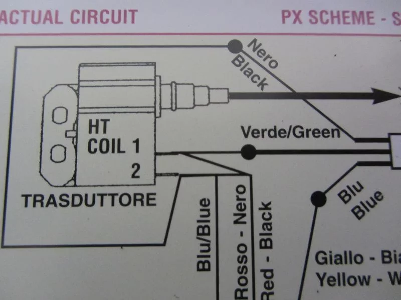
A further complication is the fact that the attached wiring diagram is not correct.
According to the wiring diagram, the mass and excitation voltage would be simply put together and distributed again to the ports 1 and 2 of the CDI.
It is of course only right to wire red/black from the stator plate to -1 – (the wider slot) which is connected with green on the wiring loom and blue to -2 – to connect (the narrow slot), which is connected with black on the wiring loom.
Likelihood of confusion exists with the cable box; here different colours need to be combined. All cables with dissolved connectors and which are energised during running engine have been provided with plug-in sleeves. The earth connection is not as potentially dangerous and can be equipped with a plug.
In order not to confuse the exciting voltage and the on-board vehicle electrical system which are both connected with a plug-in sleeve, you can use the following memory hook: „blue sea under the yellow sun“ – in practice this works really well…
For test purposes we will adjust the stator plate to the later mark of the 2 marks available.
Once we have placed all the glory in the cable box and the flywheel is mounted again, we can start the engine to control the ignition timing.
The marks for the TDC of 25 ° have been previously determined and marked by reversal measurement.
A quick check with the strobe light…
The ignition is set to 25 ° at 2000rpm. This is a satisfactory starting point for a run on the test rig.
The goal was a 25 hp engine but have a look at the diagram yourself.
Without air filter was the 148 main jet was still OK but with filter we had to use a 145 main jet and in addition to that we had to move the NAPE needle a clip on the 2nd Position from the top.
19hp and 25Nm at 6.000rpm speaks for itself. Even at 8.600rpm there are 25hp and 20Nm on the rear wheel. In this power range there will be no power loss when changing gears. It is incredibly awesome…
To get an idea of how fast this baby can get in the end, we will make another test run – HP vs. Km/h
At a speed of 140 km/h there are still 24hp left…
What do you think? Mission accomplished?
Only thing left now is to place the remaining parts again and then we are ready for a practical test on the road…


Hinterlasse einen Kommentar
An der Diskussion beteiligen?Hinterlasse uns deinen Kommentar!