Posts

Vespa PX LED-Scheinwerfer Animation

Vespa PX LED Headlight

In this Vespa tutorial video we show you how to install our Vespa PX LED headlight for the Vespa PX. The MOTO NOSTRA HighPower LED headlight itself can also be installed in other cars (Lambretta, Vespa GTS, Sprint, Rally). With the included car specific frame, the installation of the Vespa PX LED headlight as e.g. Vespa PX LED headlight is very easy

CONTENT

  1. Mounting Vespa PX headlights 00:08
  2. Electrical part / connection Vespa LED headlights 01:42
Vespa PX LED Scheinwerfer Tutorial MOTO NOSTRA LED Scheinwerfer Vespa PX

DOWNLOAD PDF Assembly instructions for printing as PDF

WHY AN LED HEADLIGHT ON THE VESPA?

The limit with conventional Bilux bulbs is on most scooters a headlight bulb with 45/45 W. The 80 W to max. 120 W ignition does not give more. The luminosity measured in lumens is less than 400 and the LED headlight has a luminosity three times as high (1300 lumens). The power consumption is only 20 W. This corresponds to the luminous efficiency of a conventional 100 Watt spotlight. This means that with a given alternator/power supply a considerably better illumination can be achieved. In addition, more capacity remains for other consumers

PARTS LIST / SHOP

Parts used in this video

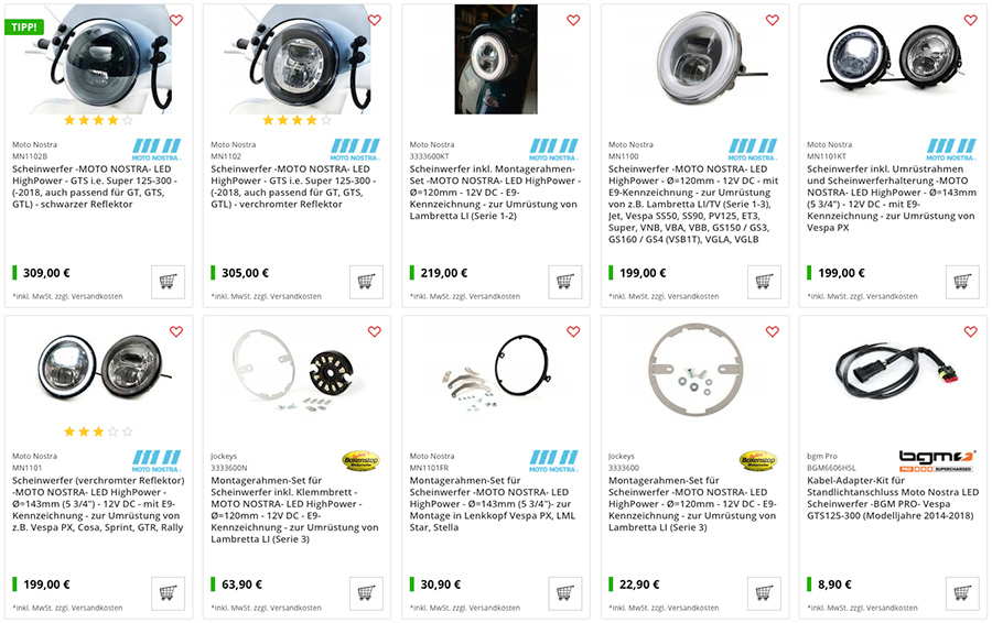
  • LED headlights incl. conversion frame Vespa PX and headlight bracket -MOTO NOSTRA- LED HighPower
    Article number: mn1101kt
  • Ignition switch -VESPA 4-cable- Vespa PX Lusso (from year 1984 up)
    Item number: 9520133
  • Light switch -GRABOR- Vespa PK125 XL/ETS, Vespa PX Elestart (1984-1998) – 10 cables (DC, models with battery, normally open)
    Item number: 9520145
  • Rubber flasher relay Vespa PX
    Item number: 3330940

MOTO NOSTA LED HEADLIGHT!

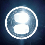
LED headlamp with E9 marking (road approval) and high-intensity main/dipped beam. Additional feature is a separately switchable position light. With a diameter of 143mm it also fits perfectly in the steering head of the PX and Cosa models as well as in the lamp bezel of e.g. Vespa Sprint, GTR and Rally.


Vespa Moto Nostra LED High Power LED Scheinwerfer

TECHNICAL DATA

Luminosity 1300 lumen Voltage: 12 Volt DC (direct current) Power consumption: 1.8A/1.3A Power consumption: 21.5W/15W/1.9W Diameter: Ø143mm Overall depth body: 54mm (measured from headlight ring without glass bulge) Overall depth overall: 79mm (measured from headlight ring without glass bulge with cable entry)

NOTE

The LED headlight works exclusively with direct current, therefore it needs a battery or another equivalent power source with 12V DC. Operation with an AC power source will result in immediate failure

Inlet timing Vespa P PE PX

In today’s video and blog it is about measuring the intake angle, also called intake timing.
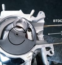
The intake angles should be within a certain range which is indicated in degrees crankshaft. The measurements always start as a fixed point from the top dead center, called OT for short.
The intake range is therefore divided into the values “before TDC” and “after TDC”, because the intake is opened before the top dead center and closed after passing the top dead center.

For a Vespa engine with rotary vane control, the values of approx. 100° F.T.S. and 65° N.T.S. have been found to be good for a good touring concept.
For very performance-oriented concepts which sometimes have to operate a higher engine speed, the values can also be significantly higher. 120° f.o.d. and up to 75° n.o.d. can be found here. The inlet angles should always be selected to match the desired concept. Here the principle is to make the intake area as large as necessary and as small as possible in order to reach the desired values.
The two-stroke heart of Platonika should be a powerful unit and therefore the inlet should be in the range of 100° F.T.O. to 65° N.T.O.

In order to determine the exact angle of one side, some tools and material are necessary.
– engine case-
crankshaft-
cylinder and piston-
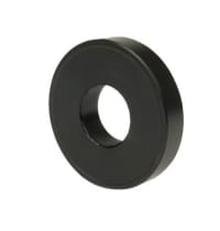
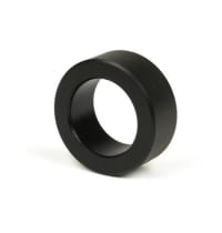
bearing dummies

BGM PRO- 613912 (25x62x12mm) BGM PRO- NBI 253815 (25x38x15mm)

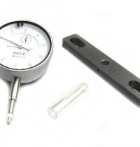
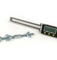
– Dial gauge with holder

Degree disc or similar measuring device

Bearing dummies

As it is very likely that the inlet area in the motor housing has to be machined to achieve the desired angles, the use of so-called bearing dummies is recommended.
With these dummies, the crankshaft can be removed from the engine case for machining as often as desired without stressing the bearing seats of the crankshaft or engine case each time and without wear and tear even before the engine is put into operation.

The bearing dummies are available for every size of the commonly used bearings in the Vespa and Lambretta range.
The first step is to insert the bearing dummies into the engine housing. Then the crankshaft is simply inserted into the bearing dummies and the engine housing is screwed into the stator housing via the stud bolts.

Measurement

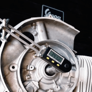
To determine the TDC, the cylinder and the piston are required. To ensure that the work is carried out smoothly, the piston is pushed into the cylinder without rings. The dial gauge is screwed onto the cylinder with the holder and thus the TDC of the crankshaft can be determined.
The alternator side of the crankshaft is fitted with a degree disc or a digital protractor. There are many different possibilities available. The easiest to handle are digital measuring tools such as the Buzz Wangle Grade Meter which does not need a reference point to the engine case.
If the crankshaft is in TDC, the degree disc, whether digital or analogue, is set to “0” and then the crankshaft is rotated to start and end of intake. The value, read on the dial, then shows when the intake is open or closed.

Increasing the intake time

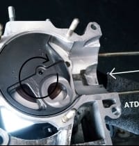
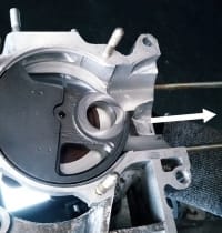
In order to bring the inlet to the desired dimension, the crankshaft is moved to the desired value and the position of the crank web is marked on the engine casing.
Once this has been done for the value before and after TDC, the engine housing can be opened again and the crankshaft can be easily removed again thanks to the position dummies.
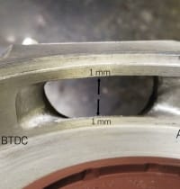
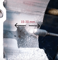
Caution is required when machining in the intake area. The surfaces sealing the rotary valve must not be less than 1 mm overlap with the crankshaft at the sides.

Once the inlet has been machined to the proper size and the crankcase has been cleaned of machining debris, the crankshaft is re-inserted for inspection.
The indicator is then used to check once again whether the desired control angles have been achieved or whether reworking is necessary.

Scooter Center Tutorial - Setting the Inlet Timing Vespa PX

The Vespa engine – the heart of Platónika – has received the desired control angles of the crankshaft in the last article

Cylinder transfer ports in the engine adapt for performance optimization

Before the complete assembly of the motor can be done, all work that generates chips must be done. Only then can the housing be cleaned.

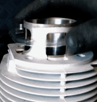
In the next step, this includes the ports of the cylinder in the engine.
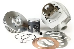
The BGM177 is designed in such a way that the cylinder functions perfectly even on the original ports.
However, in our project we took the opportunity to directly adapt the case. A better filling of the cylinder always means a higher possible torque.

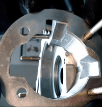
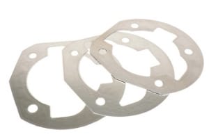
In order to transfer the contour of the overcurrent channels to the motor housing, the easiest way is to place the matching cylinder base gasket on the housing and thus transfer the contour to the housing.

The sealing surface is best marked with a foil pen. Then the contour of the overflow channels is marked with the aid of the cylinder base gasket.

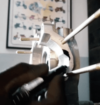
A milling cutter is then used to adapt the contour in the motor housing. It is not necessary to mill the channel exactly as deep as in the original motor housing.

The BGM 177 cylinder is designed from the basic construction so that the piston offers a sufficient cross section.
The generated surface of the adapted channel may be milled rough. Further polishing is not necessary. As long as there are no more rough corners and edges, a slightly roughened surface is perfect.

After the channels have been milled and the housing has been cleaned again, the assembly process continues

Scooter Center Tutorial Vespa PX - Modifying the transfers (activate subtitles)

How do I mount the tyres on a Vespa / Lambretta?

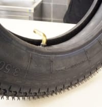
Using our bgm Classic tires as an example, we show the correct mounting of the tire (split rim).

1. Reduce friction

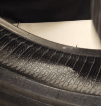
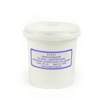
The tube inside is subject to flexing when the tire is unrolled and therefore it is useful to reduce the friction inside by talcum.
The white powder reduces the friction between the tube and the tyre and thus the wear of the tube.

A small amount of talcum powder is spread inside the tire and the tube is filled with air just enough to prevent it from expanding and also sprinkle some talcum powder on it.

2. Check the direction of travel

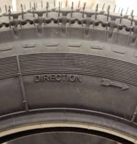
Before fitting the tube, first check that the tyre has a direction of rotation specified by the manufacturer.
This indication can be found on our bgm Classic tire in the form of an arrow on a tire sidewall and points to the direction of rotation of the tire when driving.
The tube is then inserted to match the direction of rotation of the tyre, so that the valve points to the left side in driving direction, typical for Vespa.

3. Assembly

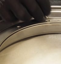
For mounting the tyre on the rim, the so-called mounting paste is a real help. With it the tyre can be pushed very far onto the rim. This makes it much easier to screw the two-piece rim together.

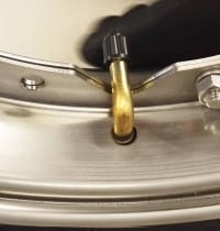
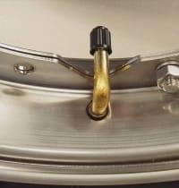
First the valve is put through the wide half of the rim and then the rim is pushed into the tyre.
The narrow half of the rim also has an opening through which the valve is accessible. When inserting the valve into the tire, make sure that the valve hole is aligned with the hole in the wide rim half.

Our bgm stainless steel rims have exchangeable bolts. Please make sure that the head of the bolt is inserted into the square to prevent rotation.

The five nuts of the rim halves are fixed crosswise with 16 – 18Nm. When fastening, make sure that the tube is not clamped between the rim halves.
Then inflate the tyre with 2 bar and check that the tyre and valve are correctly seated in the rim.

Ready

Tutorial How to assemble the bgm CLASSIC tyres for Vespa


Music: Rene Winkler from SC / NXT Level Title: First one dub 4


https://blog.scooter-center.com/neue-10-zoll-rollerreifen-von-bgm-reifen-sport-bis-180km-h-classic-bis-150km-h-made-in-germany/

How do I measure the pinch point on the cylinder head?

In our second tutorial we describe how to measure and adjust the pinch point of a bgm177 cylinder. Of course, the sequence is applicable for all other cylinders, but the dimensions can vary greatly depending on the manufacturer or the desired application of the cylinder and may differ from our dimensions in the video.

For the heart of Platónika we mounted the bgm177 cylinder dry first.
This means that the piston is initially mounted without piston rings and only with the upper bearing of the crankshaft. So if the cylinder has to be mounted several times to set the correct squeeze size, the threading of the piston rings is bypassed until the final assembly.

The bgm177 cylinder is supplied with several gaskets for the cylinder base with different thicknesses of 0.2, 0.4 and 0.6 mm.

The cylinder is mounted without a seal for the cylinder base. To map the squeeze size we use soft solder with a diameter of 2mm.

The length of the piece of solder should correspond to the diameter of the hole. A little overlength does not harm to position the soldering tin with adhesive tape on the piston, parallel to the piston pin.

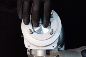
The cylinder head is mounted and fixed together with the gasket. By turning the crankshaft the piston is turned once over the TDC = top dead center. There, the solder is squeezed between the piston crown and the pinch-off surface of the cylinder head to the squeeze size, thus forming the current squeeze size.
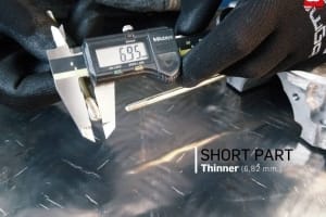
After the cylinder head is disassembled again, the crushed solder at the ends can be easily measured with the caliper gauge. In our example this results in a dimension of 0.62mm.
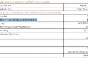
The manual of our bgm177 cylinder gives us as recommendation a squeeze size of 1mm.

How do I change the squeeze size?

In order to get to 1mm with the existing squeezing dimension of 0.62mm, a cylinder base gasket of 0.4mm must be added; to get to the desired dimension of 1mm purely by calculation.


Scooter Center Tutorial Vespa PX - Checking the piston squish (Activate subtitles)


https://blog.scooter-center.com/tutorial-stehbolzen-vespa-px/


How are stud bolts mounted on a Vespa?

In the context of our project Platonika which we are putting on the wheels together with Maryzabel, we prepare many important steps of the assembly also in videos as tutorial.
Our first tutorial shows the important differences between the different types of studs and the correct mounting.
Frequently asked questions such as

  • “Which side is screwed into the engine housing? ” or
  • “Will the stud bolt be glued in?”

are answered in this Vespa tutorial.

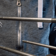
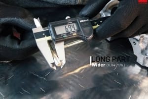
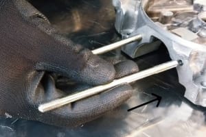
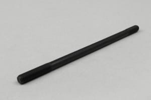
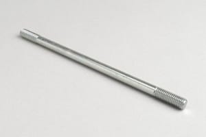
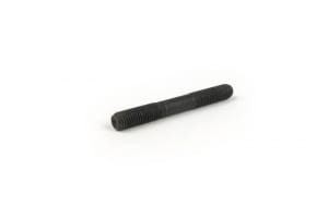
In the Vespa area the threads of the original stud bolts have a “thick” and a “thin” side.
The thread is shorter on the thin side and longer on the thick side.

The side with the thicker thread is therefore screwed into the motor housing and, provided the motor housing is intact, it clamps there automatically. The stud bolt is thus secured against self-loosening. The free length that remains above the engine housing is determined by the cylinder and cylinder head.

Different variants

Apart from the different lengths of the threads, there are other features to distinguish them.
Here are the most common ones:

-Rounded end or paragraph

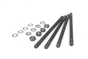
If one of the ends is rounded or distinctly offset by a stud bolt and the other end is flat, the rounded side points towards the cylinder head and the side with the flat end is screwed into the engine housing. Stud bolts with a shoulder also allow easier mounting of the washers and nuts in the cylinder head later on.

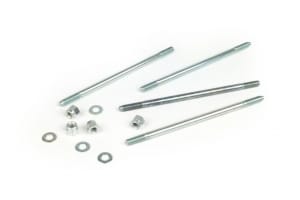
Stud bolt set -M7 x 140mm

-Marking on the shaft

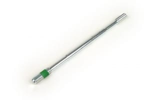
On one side of the stud bolt, a mark in the form of a ring is made below the thread. The marked side points towards the cylinder head and the side without marking is screwed into the engine housing.

Stud bolt -M8 x 160mm

-Impact or point marking on the front face

If one end face of the stud is marked, which can be a point, a star or a kind of cross, this is the free side of the stud and the opposite end is screwed into the housing.

Stud bolt -M7 x 59mm- 22-17-20mm

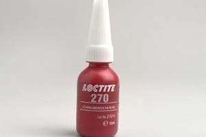
-tight screw lock

Stud bolts with manufacturer-applied screw locking are easily identified by the material. The side with the screw lock, clearly visible in blue, green or red, is screwed into the housing. The free page is blank, without any order of backup.

Stud bolt -M8 x 165mm

-Special cases

are for example stud bolts which have a clearly marked side but whose installation side to the motor housing does not have a thicker thread. These studs must be mounted with screw locking.

Stud bolt set -M7 x 158mm

Installation of the stud bolts for Vespa

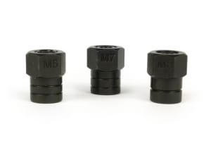
To mount the stud bolts safely, we offer this simple but ingenious stud bolt mounting set. This ensures that the stud bolt is securely fixed when screwed in and cannot simply twist through, as is often the case with two countered nuts.

Stud bolt assembly tool set -BGM PRO- M6/M7/M8


SC Tutorial Engine Casing Studs bolts (activate subtitles)

Vespa Platónika

Platónika is the name of the scooter. A Vespa PX, which we completely rebuild with new parts from the Scooter Center stock. Of course we use our best BGM parts. Benefit from our know-how, receive many tips and take a look behind the scenes.
Follow the project here on the Scooter Center blog

Watch all the videos on our YouTube channel


https://blog.scooter-center.com/das-herzstueck-vespa-platonika-bgm-177/