Vespa Polini 210, BGM 60mm ,Dellorto SI26 – tuning test engine – Pt. 4
Today we found the time to have a look at the port timings of the Polini kit.
With a 1mm base gasket one look at the degree disc shows us transfer port timings of 125° and exhaust timing of 172°. This results in a blow down timing of 23.5°.
Figures that really worth to try on the dyno and figures that should result in fast road engine with torque capable of raching high revs for good speed.
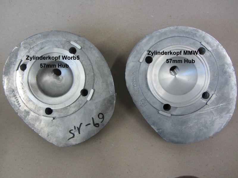
We have three different cylinder head designs to test on the engine. And this will be the first mod on the dyno.
We are going to try the MMW for 57mm stroke, the MMW for 60mmstroke as well as the Worb5 head for 57mm stroke.
On a first sight at the head we have a look at the squish clearance. The MMW 57mm version is a little bit tight at our 60mm crank. The squish would be 1mm on our setup, but well worth to try it with an additional head gasket. The MMW head for 60mm stroke is designed with a recess for the longer stroke. Used with our 1mm base gasket to achieve the right port timings we have a squish clearance of 2.7mm. So we have this head as an option if we want to try the setup without the base gasket. If we don’t use the base gasket anymore the port timings are lowered, but with the effect that the blow down timing is increasing. This is because of the greater reduction of transfer timing compared to the exhaust timing.
The Worb5 head is machined for the 57mm stroke, but with more squish clearance machined into the head. So we have a very useable squish clearance of 1.7mm without additional head gasket.
The different combustion chamber designs we will test on the dyno the next days. Can’t wait!
But the carb ist still waiting for fitment. And there are some important steps on the way to take care off.
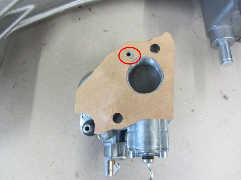
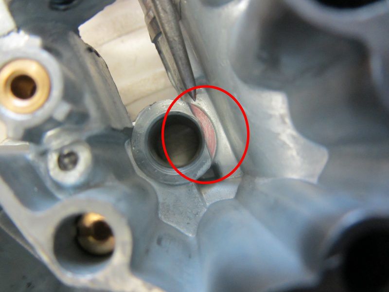
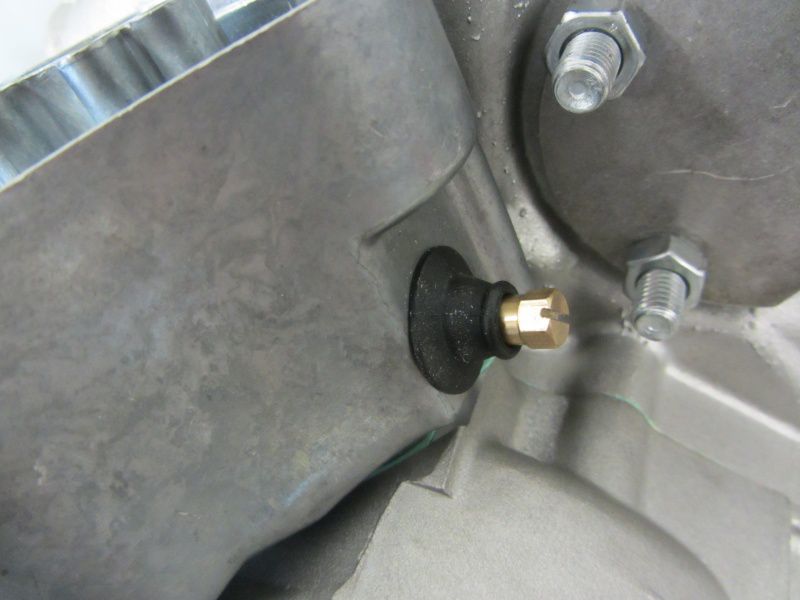
First of all you have to be careful with the use of sealer. On self-lubrication Vespas the hole marked red in the picture feeds crankshaft, barrel and flywheel side bearing wih oil. If this is blocked no oil gets in and the trouble free miles will be very limited.
The very basic design of the SI carb range is very soli. But one to watch out for is the mounting of the carb, this can easily be destroyed.
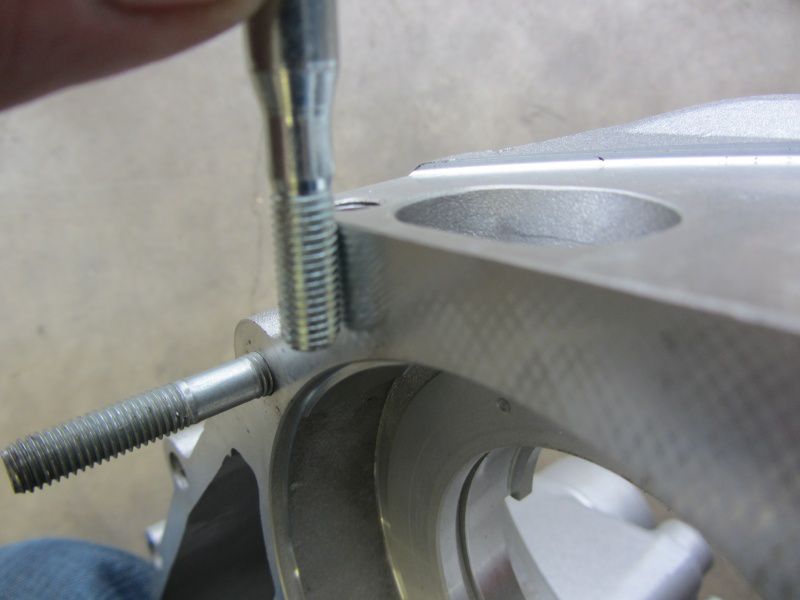
If the nuts are over tightened the carb is warped and a sticking slide is the result of it.At least the later version of the SI carb is improved in this area and the nuts can’t bend the carb so that the slide sticks.
The pictures shows this feature on the later carbs and this recess can easily be done to later SI carbs.
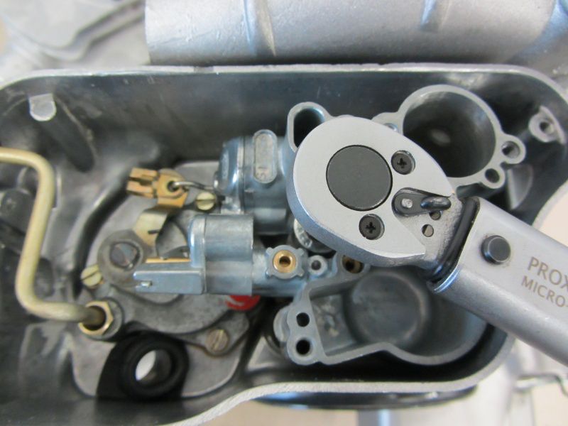
But even on the later version the carb nuts shouldn’t be tightened not more than 16-18Nm. And they shouldnot be fully tightened from the start. Instead tighten they evenly and in turn.
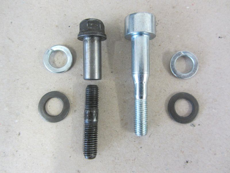
For the carb mounting there are two different version available as well.
The „old“ version with studs and sleeve nuts are there untill the SI carb was used first. The new version was introduced with self lubrication P-ranges labelled EFL, Arcobaleno or Lusso.
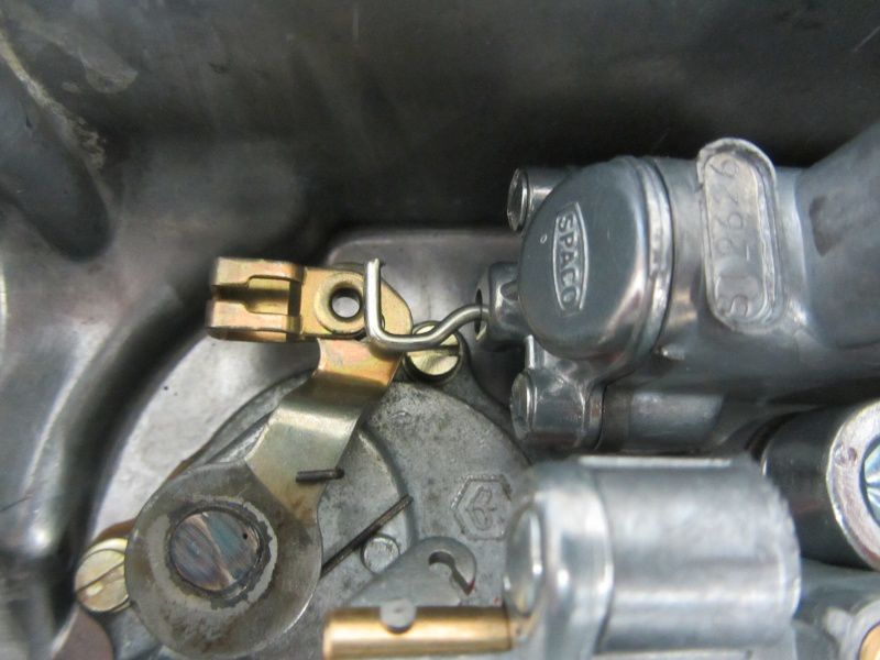
The ida came up because this was easier to fit. Carbs without self-lubrication are fitted with a very long air adjuster screw and slide hook.
Before the carb is fitted into its box we cut a slot into the air adjuster screw this makes adjustment much easier on a later point.
Damn, we spoilt it!
That happens too often. So you have to take care that the hook hits the clip of the oil pump.
If the carb is fitted like the one pictured, it simply won’t work and you foul the slide hook.
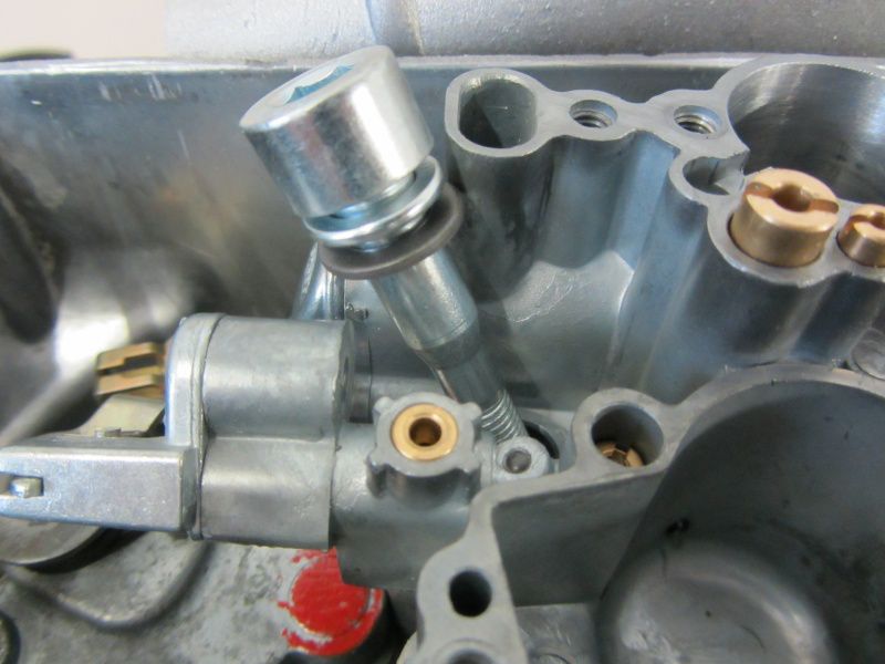
Studs for carb fitment are not supporting good work flow and Piaggio introduced the sleeved screw. But this advantage brings a risk.
The screw next to the end of the scoots is located right above the rotary valve.
If you don’t use the right washer and spring washer the rotary valve surface will for sure be destroyed.
Tighten it down in steps of 8, 12, 16 Nm.
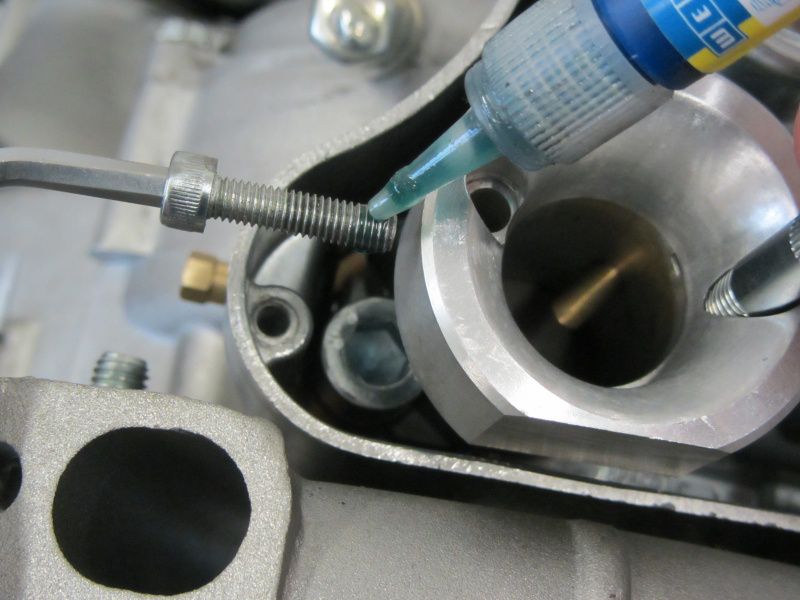
The Polini bellmouth is secured by only one screw. The idle adjustment screw can be used to get the location of the glory hole right. So simply adjust it that idle adjustment screw and the hole align.
For the dyno sessions we simply screw it to the carb. When all the jetting is done and we are happy with it, we glue the screw into place with threadlock.
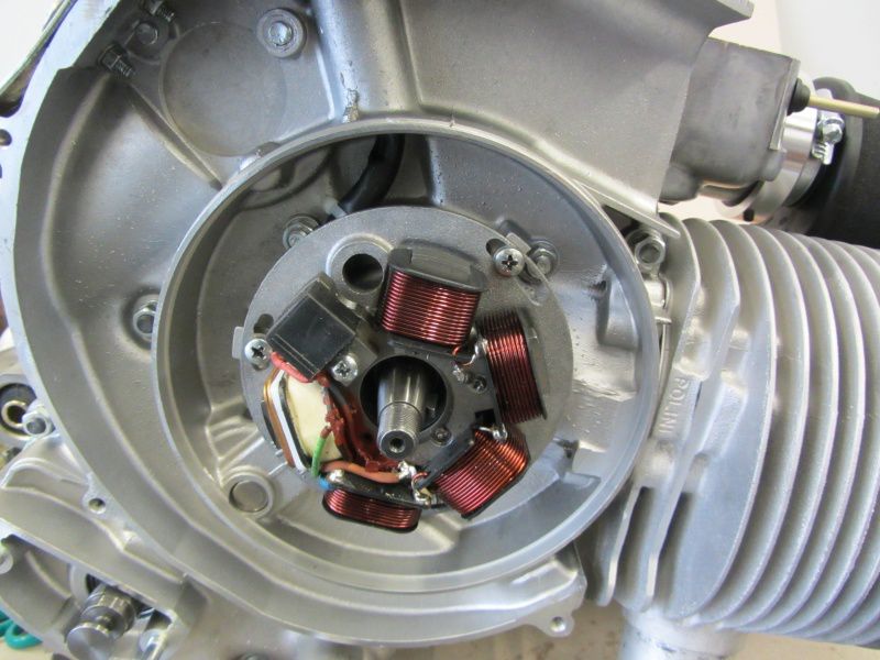
The stator plate is adjusted to 18°. This equals to th „IT“ marking at the plate.



Hinterlasse einen Kommentar
An der Diskussion beteiligen?Hinterlasse uns deinen Kommentar!