
The European Scooter Challenge (ESC) is just about to start. New engines and new scooters will be seen across the race tracks in Germany, France, Austria and Hungary.
We just had a typical K1 engine on our test rig recently which we tested for its performance and functioning.
According to the ESC rules, the stroke is limited to 51mm. Therefore, a bgm crankshaft with 51mm Stroke and 105mm rod is used.
The engine is running on a Polini Evo cylinder with 2 flaps 0.35mm carbon material Converted Polini membrane and to Straw speed intake socket. 33 Keihin carburetor is injecting the 2-stroke petrol. In order to keep the crankcase clean, the air is sucked through a Marchald air filters. The outstanding air flow rate of Marchald filters and the resulting low power dissipation make this road-proven filter very interesting for racing engines.
A Vespatronic ignition set at 24 ° -16 ° BTDC makes it smooth.
The K1 engine is fitted with a Franz exhaust. Good torque values and moderate revs make this exhaust interesting for the round circuits.
The rated power is currently supported by a XL2 clutch in combination with a DRT auxiliary shaft. More on this later. Now let's discuss the test rig curve:

All in all it is a typical Franz engine. Frequency range starts between 5500 and 6000 rev / min, peak at 9000 rev / min.
11hp at 6000rev / min uphill makes this setup really nice to drive.
With more than 20hp from 7300 to 9700 rev / min it is possible to drive within the power band due to the DRT auxiliary shaft.
Now comes the crucial point, the clutch is not the best choice for this power range. Nearly 20NM are showing us the limits of an XL2 clutch. So we have to reopen the casings and insert a Hartz4 clutchch.
Maybe this will change something regarding power and torque.
Even if a non-slip clutch does not increase any further, then at least the wear out is halted. A slipping clutch won't last many laps on the racing track. Even on the road this circumstance can lead to consequential damages.
Maybe we will find enough time to make a port map of the cylinder. Let's see.
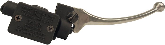
The assembly of the Vespatronic needs a lot of TLC and improved interpretation.
A further complication is the fact that the attached wiring diagram is not correct.
According to the wiring diagram, the mass and excitation voltage would be simply put together and distributed again to ports 1 and 2 of the CDI.

It is of course only right to wire red / black from the stator plate to -1 - (the wider slot) which is connected with green on the wiring loom and blue to -2 - to connect (the narrow slot), which is connected with black on the wiring loom.
 Likelihood of confusion exists with the cable box; here different colors need to be combined. All cables with dissolved connectors and which are energized during running engine have been provided with plug-in sleeves. The earth connection is not as potentially dangerous and can be equipped with a plug.
In order not to confuse the exciting voltage and the on-board vehicle electrical system which are both connected with a plug-in sleeve, you can use the following memory hook: “blue sea under the yellow sun” - in practice this works really well ...

For test purposes we will adjust the stator plate to the later mark of the 2 marks available.
 Once we have placed all the glory in the cable box and the flywheel is mounted again, we can start the engine to control the ignition timing.
The marks for the TDC of 25 ° have been previously determined and marked by reversal measurement.

A quick check with the strobe light ...
 The ignition is set to 25 ° at 2000 rpm. This is a satisfactory starting point for a run on the test rig.
The goal was a 25 hp engine but have a look at the diagram itself.
 Without air filter was the 148 main jet was still OK but with filter we had to use a 145 main jet and in addition to that we had to move the NAPE needle a clip on the 2nd position from the top.
19hp and 25Nm at 6.000rpm speaks for itself. Even at 8.600rpm there are 25hp and 20Nm on the rear wheel. In this power range there will be no power loss when changing gears. It is incredibly awesome ...
To get an idea of how fast this baby can get in the end, we will make another test run - HP vs. Km / h
 At a speed of 140 km / h there are still 24hp left ...
What do you think? Mission accomplished?
Only thing left now is to place the remaining parts again and then we are ready for a practical test on the road ...
Our good customer Sven came on Saturday to show his new Vespa Spezial.

A real stunner. And the colors work together pretty well, especially with the nice bgm PRO SC shockers!
At the dyno we checked the engine and its power output! There is no porting work done to the barrel. It went to the casings completeley Plug & Play!
The port timings are transfers 128 ° and exhaust 190 °. This gives a blow down timing of 31 °. With slightly more blow down timing the exhaust Big Bertha would work even better. Maybe we will see Sven reworking the port timings in the future !?
These are the selected engine parts:
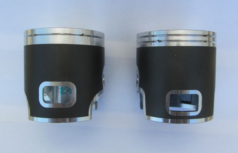
Cylinder kit: Parmakit SP09
Crankshaft: BGM 51/105
carbsKeihin PWK 33
Intake system: Polish reeds With Straw speed manifold
ignition: Vespatronic
Exhaust: Big bertha


Friday Dennis one of the guys from our Raceteam came to test his high speed circuit racing engine.
The engine is finished with these parts and the results on our P4 dyno were very impressive.
Cylinders: Parmakit 144cc, 60mm bore
Crankshaft: BGM 51/105
carbs Keihin PWM 38
Exhaust:Big bertha
This was the first dyno run and the jetting was: idle jet 52, main jet 160, needle DEG. For a first dyno run with probably some room for improvements smiles were all over. With 2.46 primary drive by DRT this should be a nice ride on fast tracks like the Nürburgring or Bilster Berg race track.

We ship climate neutral with DHL