Inlet timing Vespa P PE PX
In today's video and blog it is about measuring the intake angle, also called intake timing.
The intake angles should be within a certain range which is indicated in crankshaft degrees. The measurements always start as a fixed point from the top dead center, called OT for short.
The intake range is therefore divided into the values “before TDC” and “after TDC”, because the intake is opened before the top dead center and closed after passing the top dead center.
For a Vespa engine with rotary vane control, the values of approx. 100 ° FTS and 65 ° NTS have been found to be good for a good touring concept.
For very performance-oriented concepts which sometimes have to operate a higher engine speed, the values can also be significantly higher. 120 ° fod and up to 75 ° nod can be found here. The inlet angles should always be selected to match the desired concept. Here the principle is to make the intake area as large as necessary and as small as possible in order to reach the desired values.
The two-stroke heart of Platonika should be a powerful unit and therefore the inlet should be in the range of 100 ° FTO to 65 ° NTO
In order to determine the exact angle of one side, some tools and material are necessary.
- engine case-
crankshaft
cylinder and piston
bearing dummies
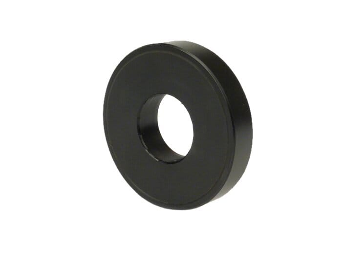
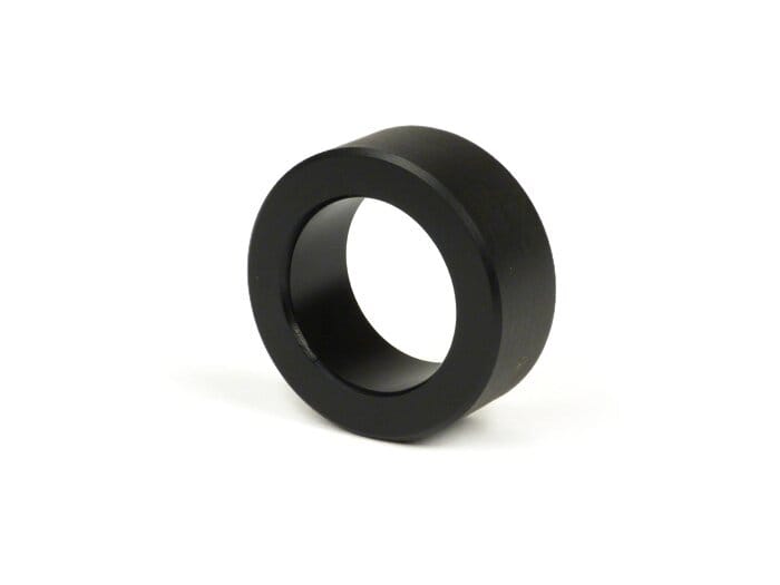
BGM PRO- 613912 (25x62x12mm) BGM PRO-NBI 253815 (25x38x15mm)
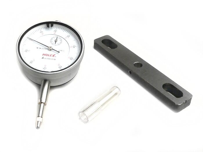
- Degree disc or similar measuring device
Bearing dummies
As it is very likely that the inlet area in the motor housing has to be machined to achieve the desired angles, the use of so-called bearing dummies is recommended.
With these dummies, the crankshaft can be removed from the engine case for machining as often as desired without stressing the bearing seats of the crankshaft or engine case each time and without wear and tear even before the engine is put into operation.
The bearing dummies are available for every size of the commonly used bearings in the Vespa and Lambretta range.
The first step is to insert the bearing dummies into the engine housing. Then the crankshaft is simply inserted into the bearing dummies and the engine housing is screwed into the stator housing via the stud bolts.
Measurement &
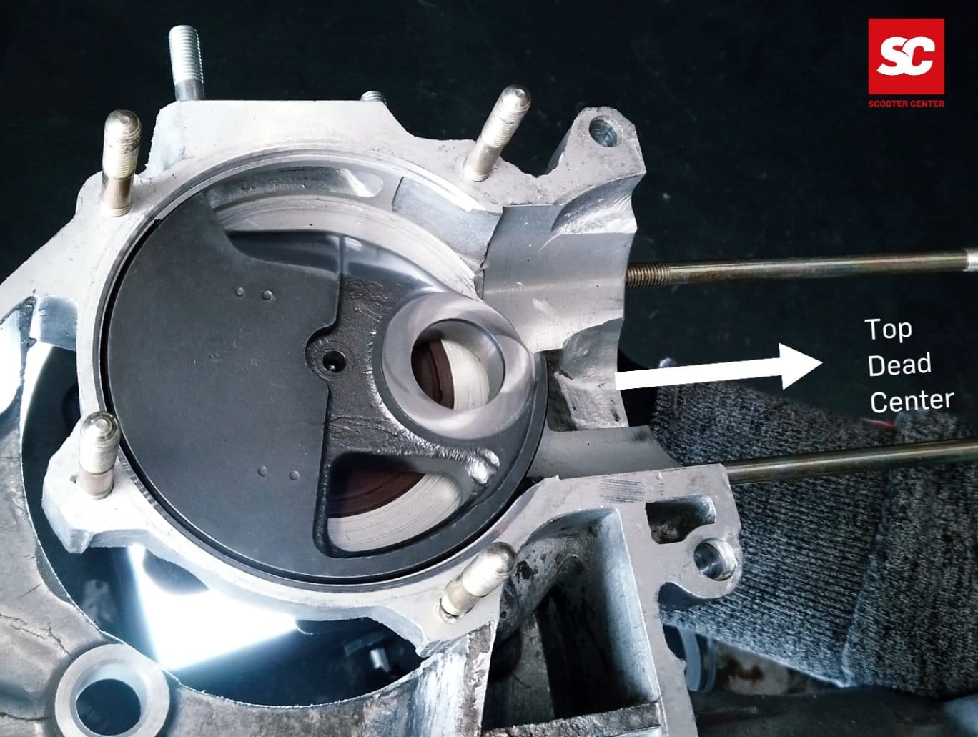
To determine the TDC, the cylinder and the piston are required. To ensure that the work is carried out smoothly, the piston is pushed into the cylinder without rings. The dial gauge is screwed onto the cylinder with the holder and thus the TDC of the crankshaft can be determined.
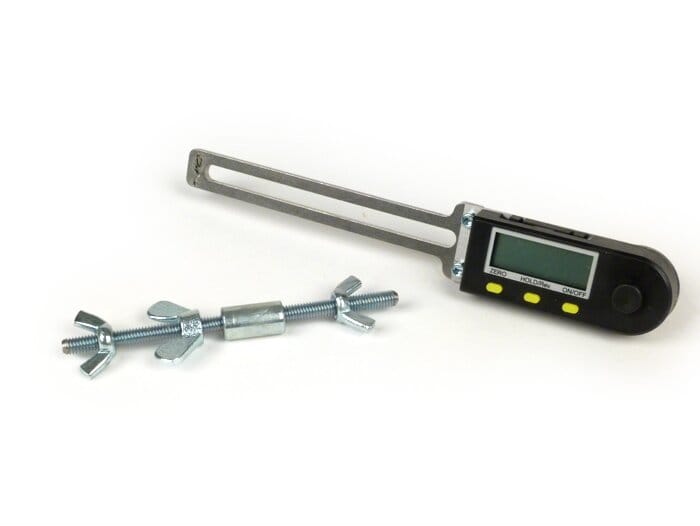
The alternator side of the crankshaft is fitted with a degree disc or a digital protractor. There are many different possibilities available. The easiest to handle are digital measuring tools such as the Buzz Wangle Grade meter which does not need a reference point to the engine case.
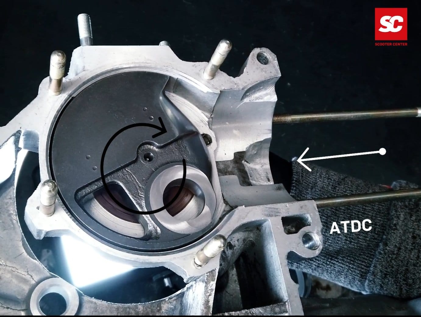
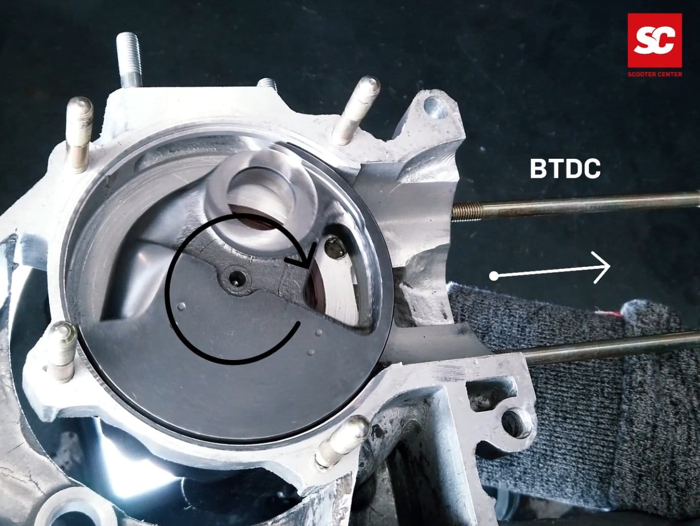
If the crankshaft is in TDC, the degree disc, whether digital or analogue, is set to “0” and then the crankshaft is rotated to start and end of intake. The value, read on the dial, then shows when the intake is open or closed.
Increasing the intake time
In order to bring the inlet to the desired dimension, the crankshaft is moved to the desired value and the position of the crank web is marked on the engine casing.
Once this has been done for the value before and after TDC, the engine housing can be opened again and the crankshaft can be easily removed again thanks to the position dummies.
Caution is required when machining in the intake area. The surfaces sealing the rotary valve must not be less than 1 mm overlap with the crankshaft at the sides.

Once the inlet has been machined to the proper size and the crankcase has been cleaned of machining debris, the crankshaft is re-inserted for inspection.
The indicator is then used to check once again whether the desired control angles have been achieved or whether reworking is necessary.