Our test engine ran warm and the spraying with a secondary nozzle 48/160, air correction nozzle 160, mixing tube BE3 and a main nozzle of 140 seems to work for now. Now we can do the first runs to measure performance.
To do this, the overall ratio in 3rd gear is measured 2-3 times on the P4. In our case, the overall ratio is 3,21. We can re-enter this value manually in later runs in order to eliminate errors when measuring and to obtain consistent, reproducible results.
So we do the first 3 runs. If all runs are almost congruent, we can assume that the experiment worked well and that we “experienced” a comparable result.
Here is the first result.

It's nice to see that, as expected, the engine makes a lot of torque available very early on. This impression is also confirmed during a test drive on the road. In terms of the tractor, the engine pushes off very nicely at 3500 rpm, i.e. practically at increased idling speed, with 17 Nm.
Besides, the unobtrusive suction noise of the Polini solution is pleasing. With the adapter, Polini has incorporated a small but important trick. The sound waves break effectively on the inner edge of the adapter and thus become a sonorous, inconspicuous suction noise.
Back on the test bench, we mount the MMW cylinder head on our 210 Polini.
For the tests on the test bench, we put a 0,5mm and 0,2mm thick Polini cylinder head gasket under it so that we get a comparable squeeze dimension of 1,70mm. It is absolutely advisable not to underlay an O-ring sealed cylinder head with an additional gasket. The material of the solid seal could be pressed into the O-ring groove by the surface pressure in connection with the thermal load on the cylinder head, damage it and thus render it unusable.
For test purposes, however, this is possible without any problems, after all we are not planning a circumnavigation of the world but a series of tests. Should the shape of the combustion chamber of the MMW cylinder head prove to be useful, we can think about a necessary change at this point.
After 3 more runs we get the following nice, colorful mountain range in direct comparison.

RED: MMW

BLUE: Worb5

The extra power of the MMW cylinder head results on the one hand from the slightly higher compression and most likely from the different combustion chamber geometry compared to the Worb5 cylinder head. Since we both brought the cylinder heads designed for a 57mm stroke to the same crush dimension of 1,7mm, one can speak of a fair comparison here.
The maximum torque is as usual at 4700rpm and increases with the MMW cylinder head to a whopping 22Nm.
At 7000rpm there are still 17PS and 17Nm. Certainly good to achieve an average high travel speed.
We save ourselves the experiment with the MMW cylinder head for 60mm stroke. Not out of laziness, but because we already know that the engine responds positively to a little more compression.
Because with the same combustion chamber geometry, but with the compression reduced due to the larger crush dimension, no increase in output or torque is to be expected.
A little more band with higher torque and more power in the higher speed range would be desirable. This would enable us to better overcome the exponentially growing driving resistance with increasing speed.
Mmmmh, what else could you try now? Actually already suffering at a high level? After all, we are talking about an engine which, thanks to its well-considered selection of components and its assembly, provides quite a remarkable performance.
With a look through the test stand room, we discover our test prototype of the bgm bigbox -

we should still try that.

Tomorrow… (:

Only a few more steps separate us from hooking the engine into a test vehicle.

As a test victim for our Polini engine, we use the familiar one Silver Fern .
When assembling the pole wheel, make sure that the groove is the Crescent wedge hits exactly.

Then the Flywheel nut tightened with 65Nm. washer do not forget !

The rear one brake drum is initially only attached and fixed with the nut.

As soon as the rear brake is functional, the brake drum can be attached with 110Nm. Fuse cage and split pin must of course not be missing.

We still connect the controls on the handlebars to the engine, that is Gas-, switching and Clutch will attached and adjusted.

The security game on clutch lever should be between 1,5mm and 2mm in order to avoid the clutch cable being actuated when shifting into higher gears and thus the Pressure mushroom on the pressure plate works and the Clutch possibly even actuated.

Olive oil and fuel hose follow. The air bubble in the oil hose is intentional. When connecting for the first time, you can check whether the oil is being pumped into the carburettor.

However, the air bubble should not be larger than shown here, otherwise there is a risk that the pump will run empty and no more oil will be transported towards the carburetor.

For the “first firing” we fill the tank with 1 liter of super in a mixture of 1:50. This amount of fuel should be enough to bridge the gap until the oil pump delivers the valuable lubricant.

The last missing parts are the Flywheel and the Cylinder hood.

Then it's fire free!

After warming up for a few minutes, we first shift through all gears once and test whether all gears hold and the clutch disengages properly.

A quick look at the oil hose reveals - the pump is running.

So then, first attempt on the test bench with the following setup:
- Polini 210, Outlet, piston and overflow channels are not machined, Spacer cylinder base 1mm.

-YES 26, Cosa float chamber ceilingl with additional bore, nozzle holder also with additional bore

- Nozzles 48/160 - 160-BE3-a set Main jets to play around

-Inlet area freed from the disturbing edges, the seals adapted to the new contour. Polini velocity stacks with adapter and Polini air filter.

-bgm-Pro 60mm crankshaft

-SIP Road exhaust

- Ignition 18 ° bc

-Cylinder head Worb5

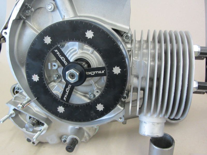
To be on the safe side, we check them Ignition adjustment by reversal measurement. If the tolerances on the crankshaft, pole wheel and base plate are correct, the markings should be on top of each other when flashing. This time we made the 18 ° marking on the pole wheel.

Ok, the ignition is correct - then nothing stands in the way of the first test run ...

Now it starts with measuring the timing and the final steps before the first test bench runs.

With a 1mm Cylinder base gasket tells us that Degree disc an overflow angle of 125 ° and an outlet angle of 172 °.

Values ​​with which you should definitely try a few times.

We also try out 3 different cylinder heads.

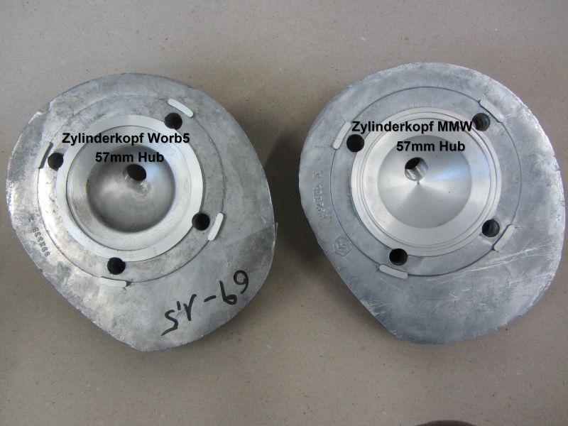
MMW for 57 mm and 60 mm Hub and one wrob 5 Cylinder head for 57mm stroke.

At first we only consider the squeeze dimension. The MMW head for 57mm stroke is, as expected, a bit tight at 1,0mm, a test with an additional cylinder head gasket from 0,5 mm or 0,8 mm is still possible. The head for 60mm stroke is practically designed as a head gasket variant and compensates for the stroke difference of 1,5mm through the combustion chamber, so the squeeze dimension here is, as expected, quite high at 2,7mm.

However, the MMW cylinder head for 60mm stroke also leaves the scope to lower the cylinder again. This shortens all steering angles, but this results in more foresight, which could perhaps have a positive effect on driving behavior.

The cylinder head from Worb5 was also made for a 57mm stroke, as is well known, the squeeze dimension on 57mm stroke with this head is quite large. In our case, this results in a quite usable squeeze dimension of 60mm with a 1,7mm stroke without an additional cylinder head gasket.

To what extent the different combustion chamber geometries then affect the power delivery, we will determine on our test bench.

The assembly of the carburetor is also part of completing the engine.

Obviously a fairly trivial topic, but you can skilfully screw it wrong here too.

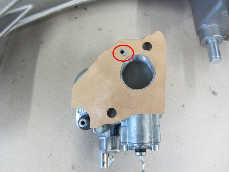
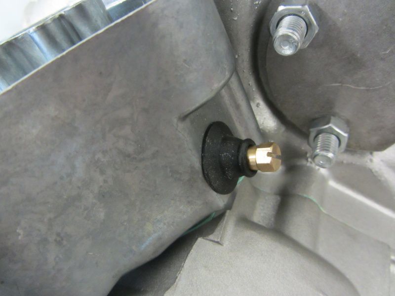
Friends of the generous use of sealant should exercise caution. The channel on the underside of the carburetor pan and the oil hole in the carburetor (marked in red here) must remain free on engines with separate lubrication. If the supply routes are closed, the crankshaft, alternator bearings and cylinders run without oil; and usually not for long '.

The frugal SI carburetor itself is very sensitive to incorrect attachment.

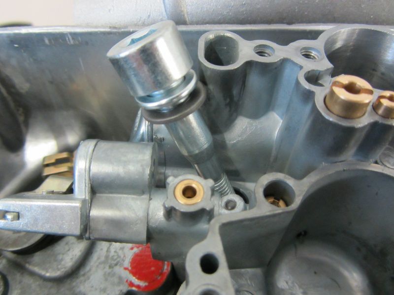
If you overdo it when tightening the screws, you could later struggle with a jammed slide. All newer SI carburettors have already been improved so that the screw head can no longer act directly on the slide guide.

To be recognized by a small undercut. This trick can also be applied to the older carburettors.

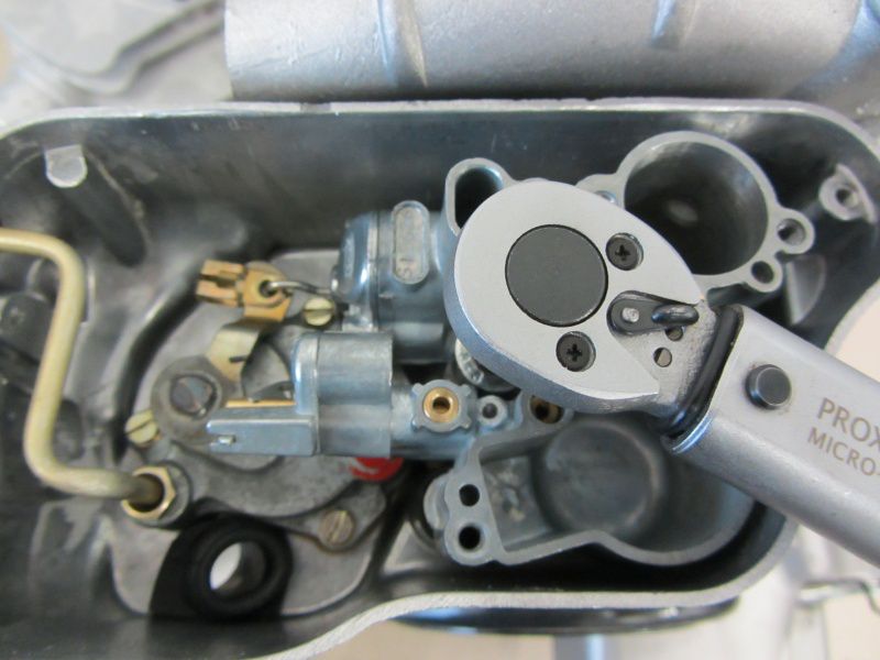
But even in spite of this preventive measure, you should stick to the torque of 16-18Nm when tightening the screws alternately.

There are 2 variants of the carburetor attachment that can be used.

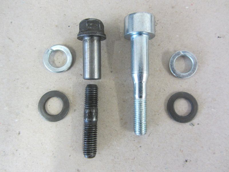
The “old” version with studs and sleeve nuts exists since Largeframes were equipped with SI carburetors there. The newer variant with a Set screw only came up with the Lusso or better the models with separate lubrication.

The reason for this is simply the ease of installation. Carburettors with separate lubrication are noticeably long due to better accessibility Mixture adjustment screw and an Push rod to hook in equipped. For use on engines with mixed lubrication, the pull bar can also be easily exchanged. Before the carburetor in his tub Taking a stand, we cut the mixture adjustment screw with a file. This will make it easier to set up later.

Shit, besides ...

That happens often and with pleasure.

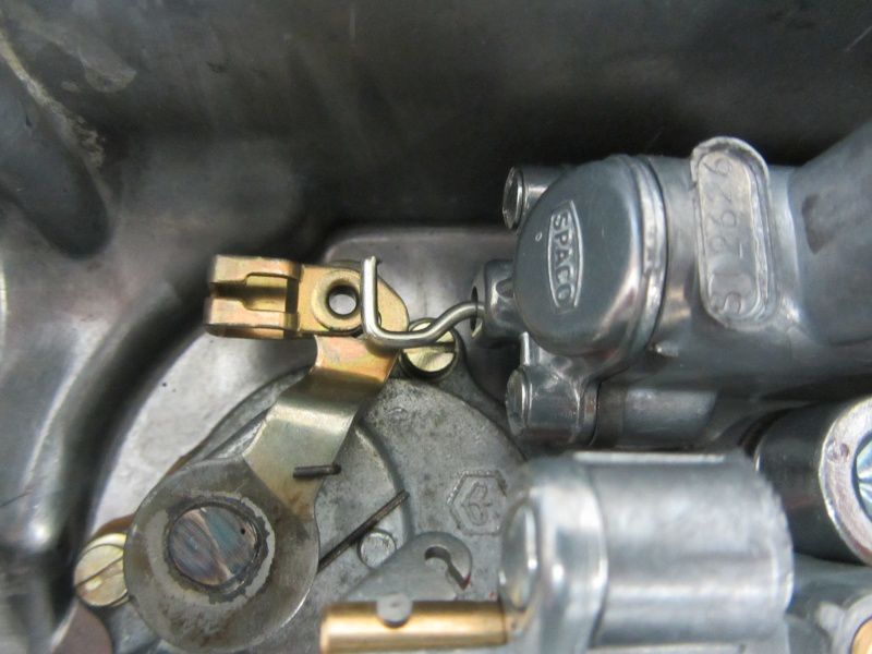
When inserting the carburetor, make sure that the hook catches the tab of the oil pump.

If the carburettor is screwed tight as shown in the picture below, on the one hand the slide rod will be damaged and on the other hand, the carburetor would have been successfully disabled.

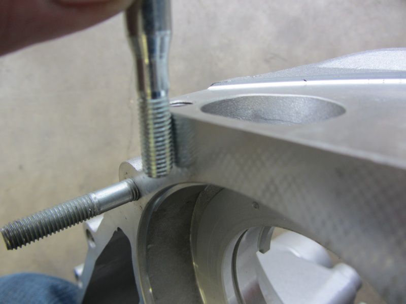
Stud bolts for attaching the carburettor would be a hindrance when inserting, so Piaggio came up with the idea of ​​the set screws. Unfortunately, there is a small risk in simplifying it.

The screw at the rear in the direction of travel sits directly above the rotary valve surface.

At this point we forget the required one slices or Snap ring to use, the rotary valve will inevitably be damaged.

The carburetor is attached in steps of 8, 12, 16Nm.

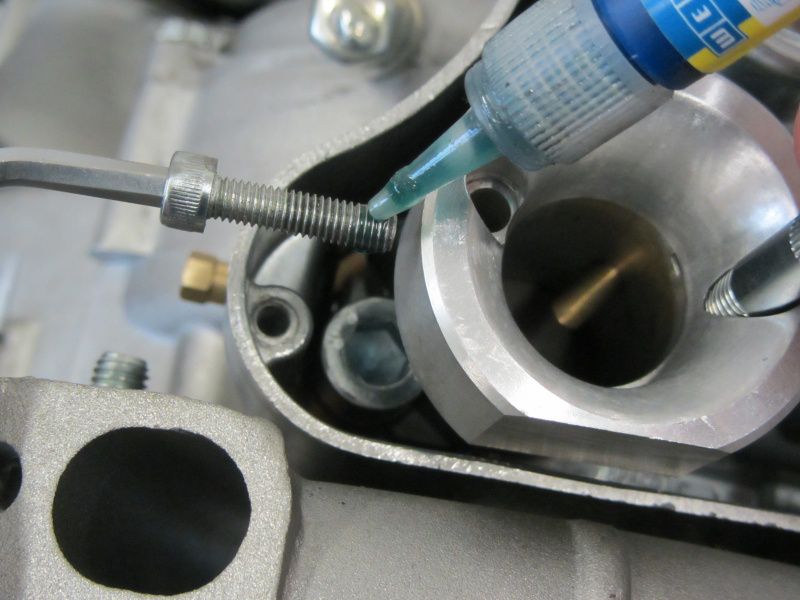
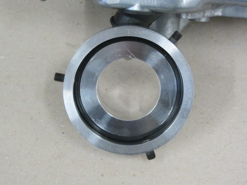
The Polini funnel is only fixed with a screw. the Idle speed screw is only used for installation orientation, as the funnel has a through-hole at this point.

For the test stand, we are content with simply attaching the single screw due to the expected nozzle change. However, as soon as a suitable carburetor setting has been found,
you should get the screw with threadlocking fix.

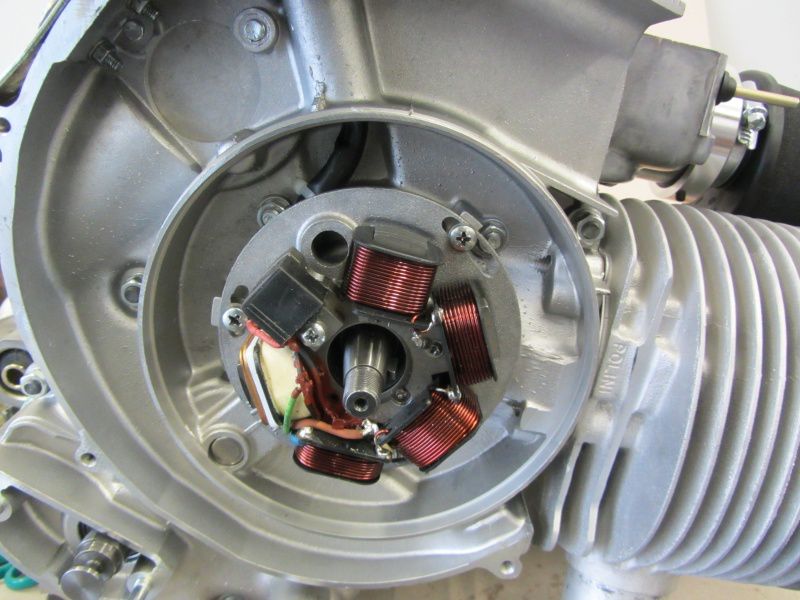
The Ignition stator For the first test runs we set it to the “IT” marking, i.e. an ignition point of 18 ° before the end of the day.

The carburetor and intake area are prepared.

Now we can fill the engine with the parts we still need.

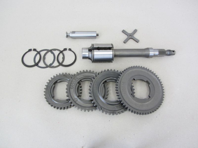
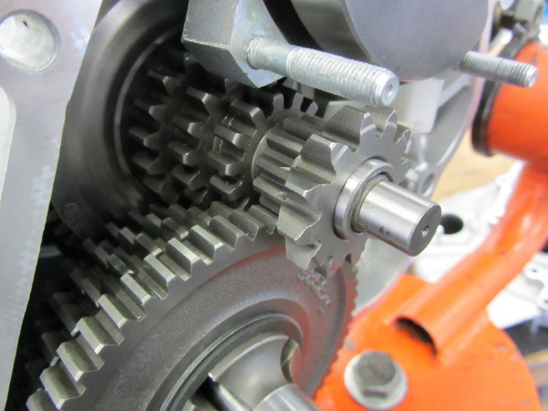
The 4 speed levels are in the form of a Px200 transmission built-in.

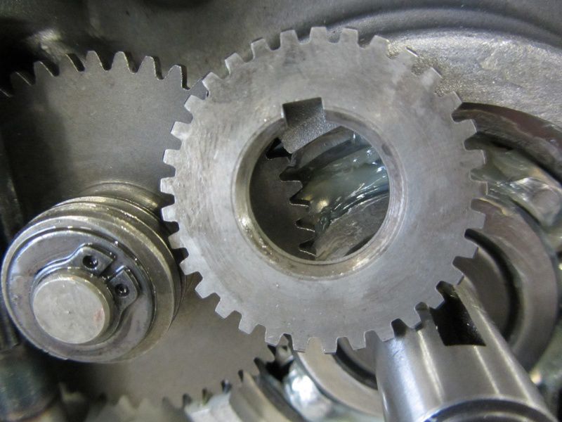
Switch cross and gear wheels are mounted accordingly.

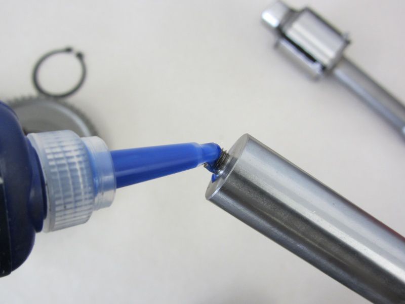
The switch cross should be something threadlocking . use

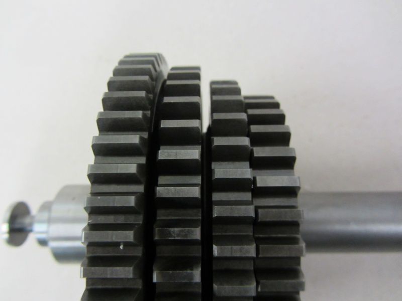
Gear wheels, Seeger and Shoulder rings can then then be draped to create a pretty overall picture.

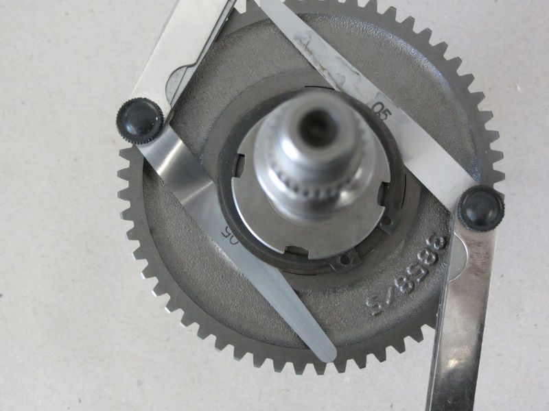
The play of the gear wheels should be in the range of 0,05mm-0,15mm during installation. It is best to control the existing game with 2 Feeler gauges. With new shoulder rings you can choose the game tighter, since the bearing surfaces of the shoulder rings shrink even more over the first few kilometers than with already used shoulder rings.

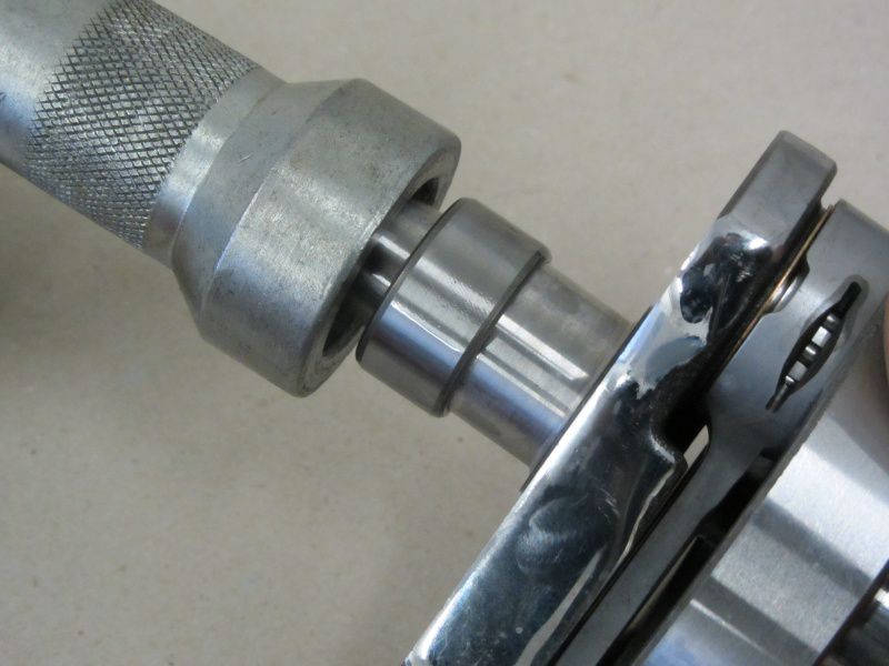
The crankshaft still gets even with that suitable tool missed the inner ring of the alternator bearing.

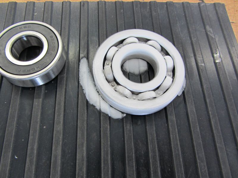
And the Ball bearing set implanted.

The ball bearings are with Cooler spray cooled and gently brought into your bearing seats by heating the housing halves.

Exceptions are the two needle bearings in the “small” half of the alternator housing.

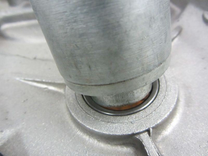
The Alternator bearings should be safe with the matching tool be guided.

The B188Bearings for the main shaft have to be given a little extra, 1000gr. in shape a hammer should be enough as gentle intercession.

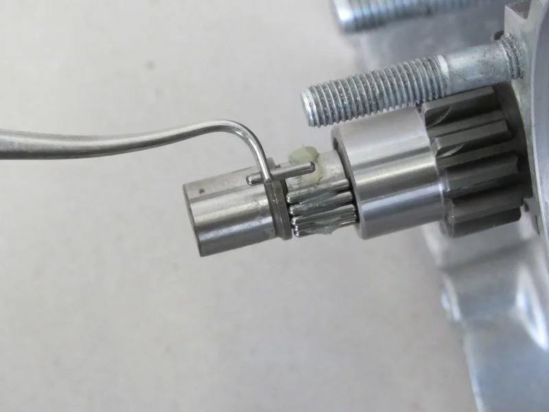
Once all the bearings have found their place, they will Shaft seals assembled and puzzles with the Needles of spurious consequences. The individual needles with fat fixing helps a lot. You should still have a steady hand. Don't forget to count, 21 needles should work here.

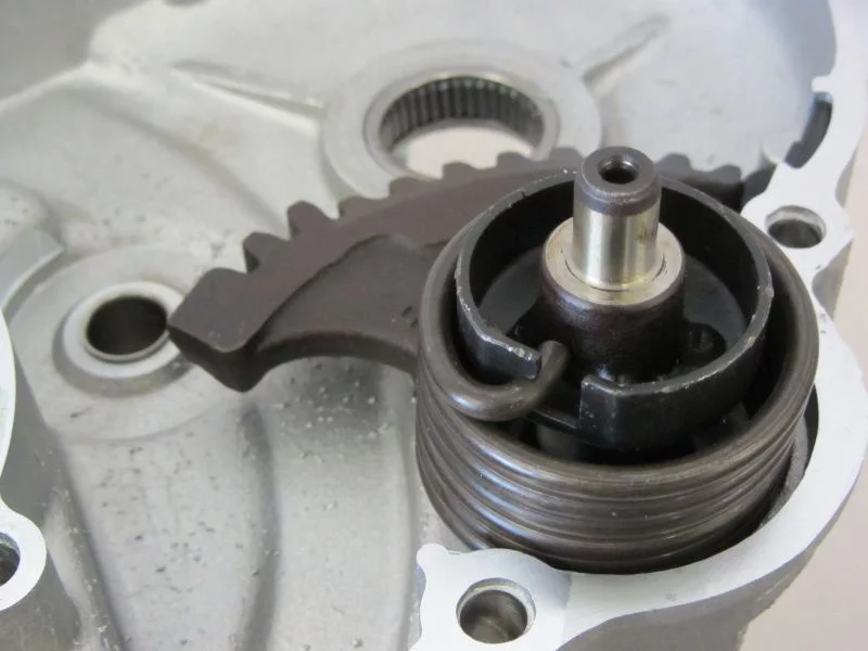
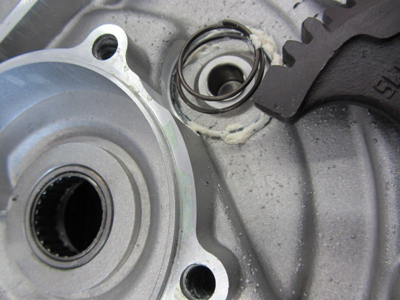
Kick starter pinion and segment are the last missing components.

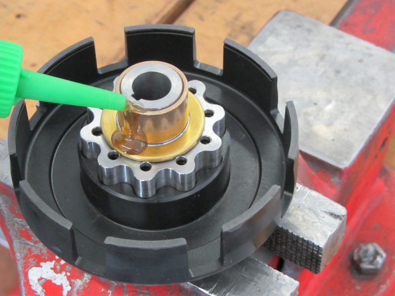
Do not forget! the Pressure spring the kickstarter sprocket is best glued in with grease.

The crankshaft is installed and the housing assembled.

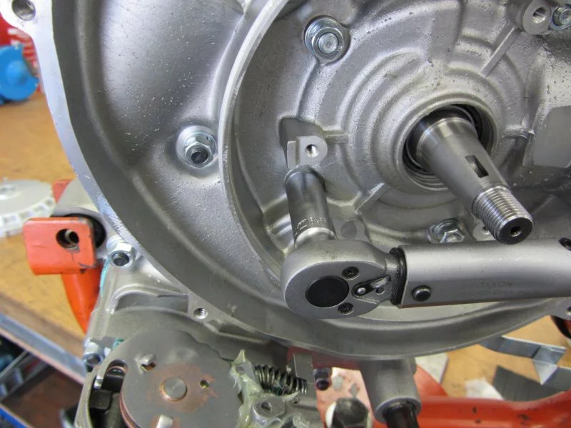
With the torque wrench, everyone will Housing bolt evenly tightened.

The oil pump drive is installed.

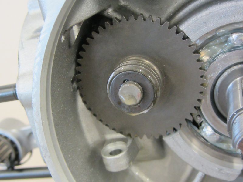
The Worm wheel is from 2 Thrust washers flanked. The one is missing in the picture below Seeger ring serves to secure the worm wheel.

Nachdem die Oil pump shaft mounted with a little oil can do that pinion placed on the crankshaft and mounted the clutch. Most crankshafts have a small radius towards the coupling stub on the coupling side. Therefore, the bevel of the pinion should point towards the crankshaft during assembly.

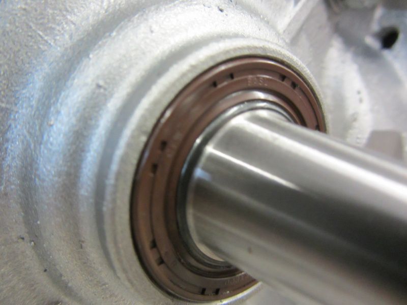
Here in the installed state you can see how nicely the dust lip on the wider sealing surface of the bgm crankshaft protects the actual sealing lip.

The most important link between the gearbox and the crank drive is the clutch.

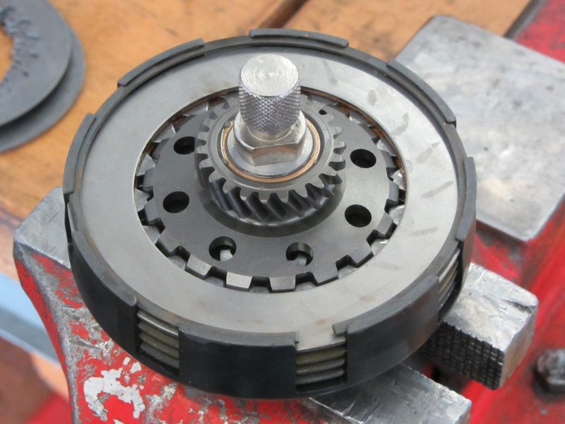
Therefore we rely on the tried and tested bgm Superstrong clutch.

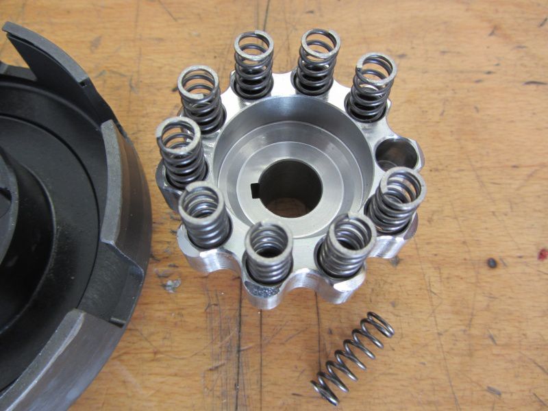
Designed for 10 springs, the Superstrong offers a lot of possibilities to vary the spring stiffness.

In our case we are using 10 XL feathers.

Dhe shaft-toothed hub is used with oil.

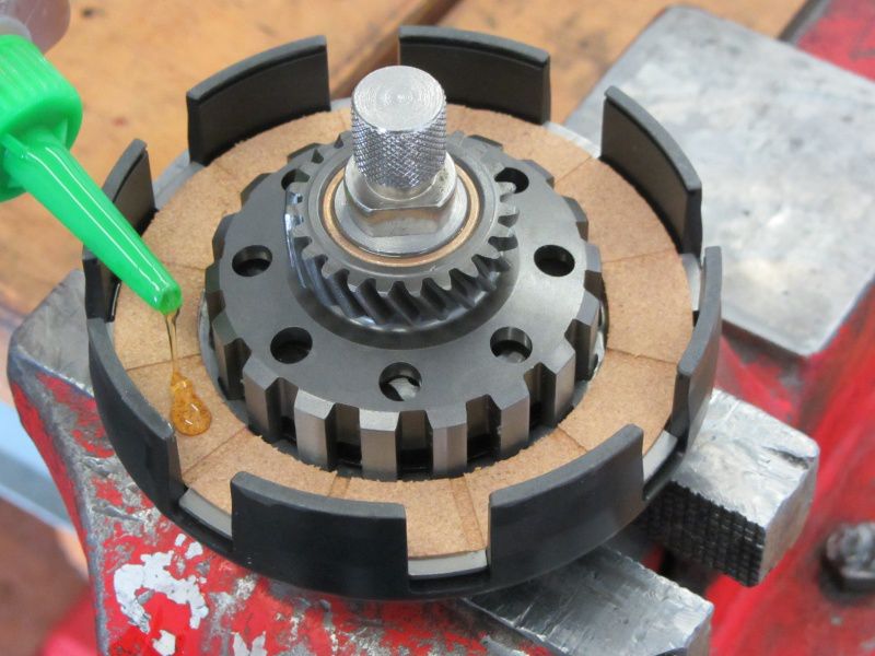
Clutch pinion and Topping packt with steel discs consequences.

When installing the pads for the first time, you should add a little oil.

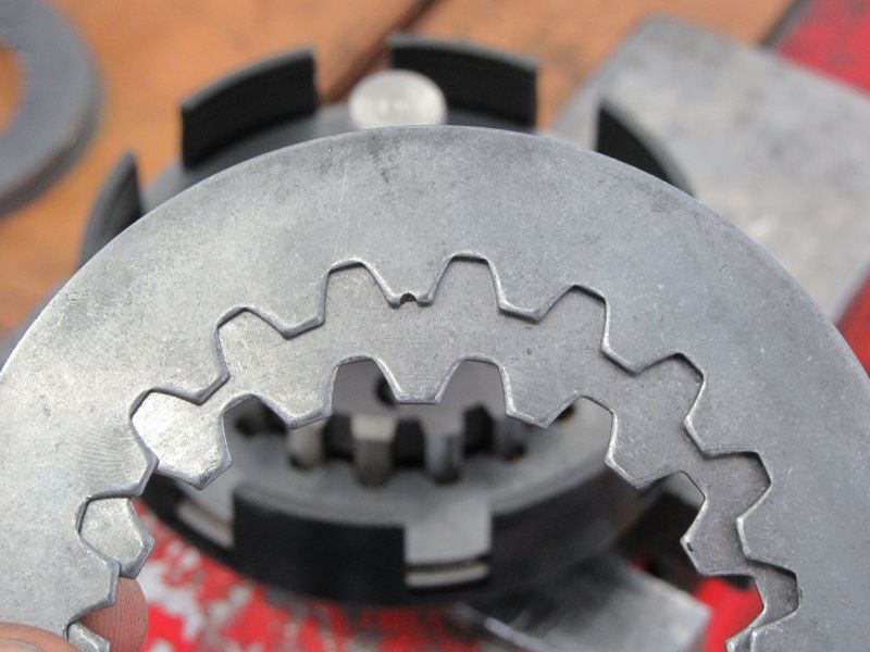
With the steel disks you have to pay attention to the positioning of the Washer with the notches respect, think highly of.

This is deliberately deformed by a few 1/10 mm in order to immediately create the clearance when the clutch is actuated so that the clutch separates cleanly.

Is the topping package and the Locking ring mounted, the coupling is ready for installation.

By the way, all complete bgm-Superstrong couplings are pre-assembled for you in exactly this way. Including adjustment of the clearance and control of the freedom of movement.

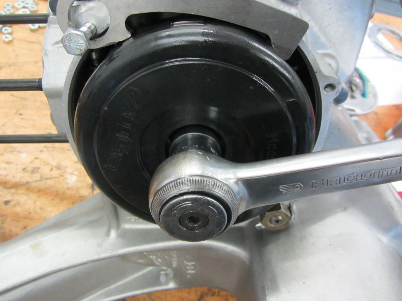
The self-locking Collar nut we fastened with 60Nm.

Now that the engine has been put together so far, the cylinder can be attached for testing purposes to measure the control angle. Nice job for tomorrow :-)

Also the Polini velocity stacks and Dell Orto SI 26 let's take a closer look. Why do you need this funnel anyway?

In the end it simply helps the carburetor to suck in more air and to ensure a better filling with fresh gases. More ignitable fresh gases in the cylinder ensure more available power.

A larger volume of air must of course also be fed with more fuel. That's why Polini has already put one in the intake trumpet for the 200 engines 138 main jet at.

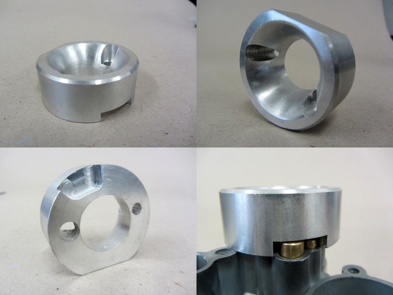
There is also an undercut in the funnel in the area above the auxiliary and air nozzle. This fulfills the task of supplying air, similar to the effect of drilling open the original SI filter base arises and helps the carburetor to a significantly better tunability and throttle response.

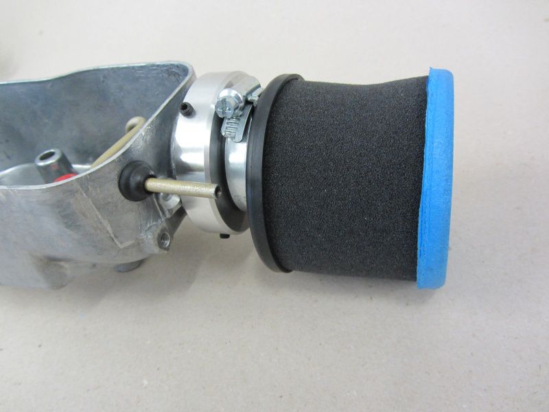
Since the actual air filter is no longer required by using the Polini funnel, Polini has come up with a clever solution.

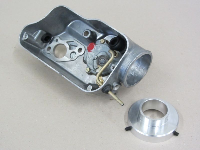
An air filter is mounted on an adapter for the carburetor pan.

When assembling the adapter ring you should make sure that you have all the grub screws of the adapter, as well as all necessary connections on the carburetor pan for Gas- and Choke cable as well as the connection for the Oil hose which can achieve separate lubrication.

The fact that Polini has already included a 138 main nozzle in the funnel set gives an idea of ​​how much the air throughput could be increased. From a main nozzle size of approx. 130 you should take some precautions with the SI carburettor to keep the fuel supply constant.

First of all, a continuity test of the fuel tap should be on the program. For performance-oriented engines, the fuel tap should provide a flow rate of at least 280-300ml / min. Most standard petrol taps fail in this discipline, our remedy is here Faster Flow fuel tap.

Except for a well-functioning tank ventilation in the filler cap, can no longer be optimized in the tank area.

In the carburetor itself, however, there are also other bottlenecks which can have an unpleasant effect on the fuel balance.

The small float chamber of the SI carburetor must be constantly supplied with petrol under full load.

Unfortunately, the energy-giving juice must first pass through the eye of the needle "float needle valve".

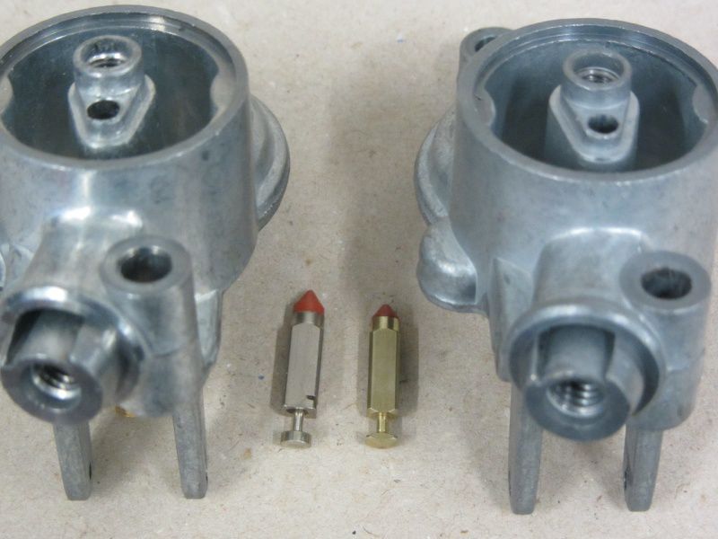
The best way to do this is to swap it Float chamber cover against the variant of the Cosa carburetor .

On the right the normal SI cover, on the left the Cosa version.

In addition to the larger float needle, the valve bore and the needle seat are also made significantly larger.

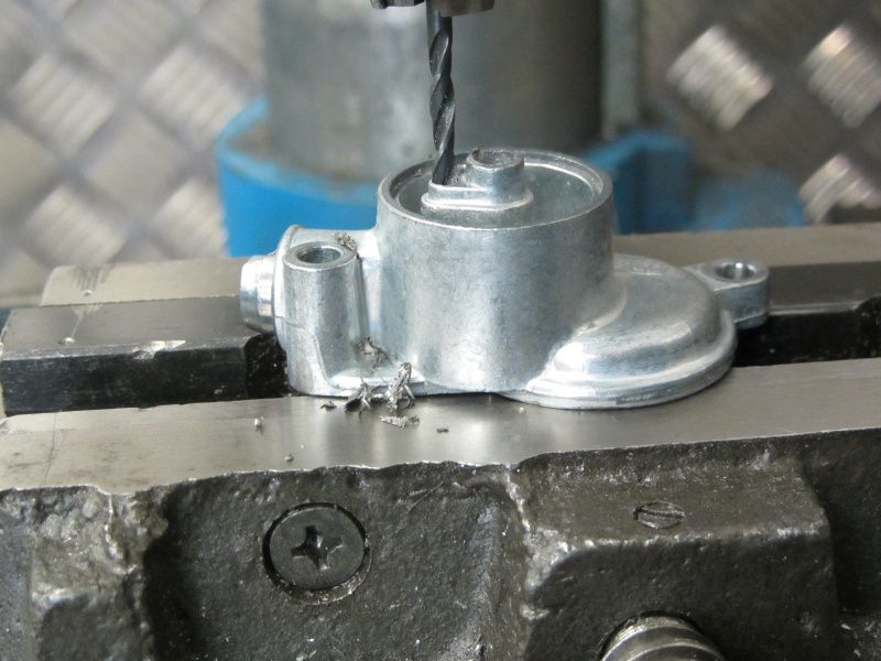
We are also increasing the inlet to the float needle valve to 3mm.

Now we have done everything so that the float chamber is full of juice in every driving situation.

However, the carburetor still has a hidden bottleneck in store for us.

The inlet from the float chamber to the nozzle assembly.

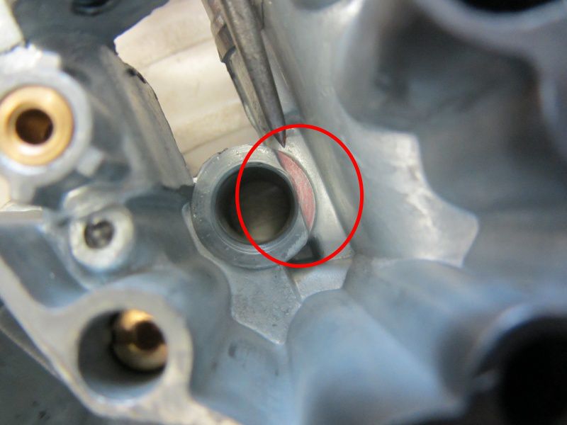
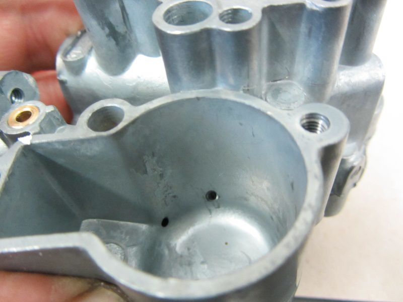
The fuel must rush to the main jet as quickly as possible through the tiny hole in the center of the picture.

The crux of the matter here is that the bore is too small at 1,5mm from a certain main nozzle area. Approximately comparable to a 150 main jet. In order to ensure free travel here, the channel is drilled to 2mm. The hole on the left is only used to feed the choke system and does not require any further attention.

With the appearance of the Polini 210, a dream has come true for many scooter riders.

Proven Polini torque in an aluminum dress from the speed basement with little effort. On the first "test engine" with a stroke of 57mm, this assumption was consistently confirmed.

Polini has recently started offering other interesting toys to increase performance and, above all, to increase driving pleasure. In addition to the already available Intake funnel for the original SI carburetor, Polini announced the appearance of a new cylinder specially designed for a 60mm stroke along with a matching 60mm stroke crankshaft, so a Polini 221.

Inspired by these developments, we decided to build a complete engine for test purposes. First with the 210 Polini, this will give way to the big brother that will hopefully be available soon.

So we first drag the following toys to our test stand, or first of all to the workshop for assembly.

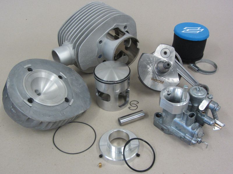
Cylinder kit Polini 210, cylinder head MMW and Worb5, intake manifold Polini for SI carburetor, 26mm SI carburetor and a crankshaft bgm PRO 60mm stroke.

We take a closer look at all parts and prepare everything for installation.

First consideration is the motor housing, this is where all the toys will move in later.

New PX200 motor housings are currently only available from Malossi. Except for the distribution channel, nothing has changed on the motor housing.

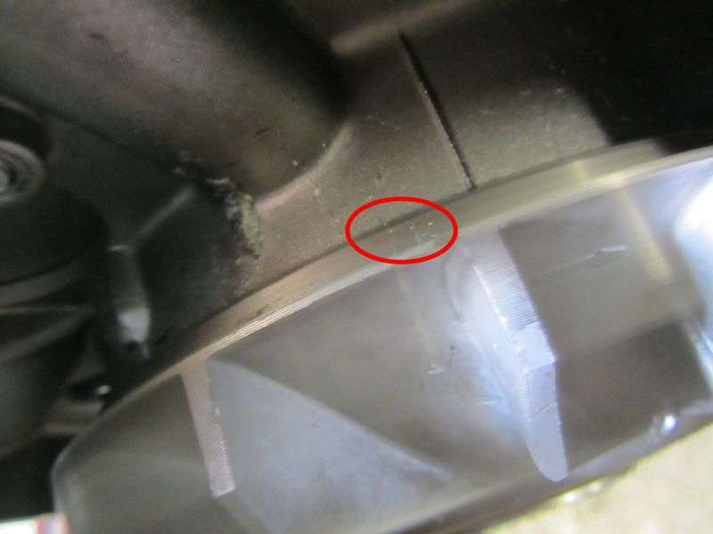
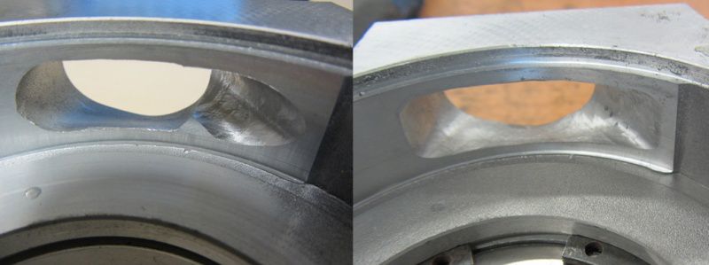
We pay special attention to the rotary valve inlet. In order not to obstruct the fast-flowing fresh gases there too much, we remove the factory-made burrs and edges. Furthermore, the inlet will not be revised.

At the heart of the engine, we use the tried and tested BGM crankshaft. Optimal intake control angles will help our test engine run smoothly over a wide speed range.

The BGM crankshaft also offers the option of installing an FPM shaft sealing ring with a dust lip on the alternator side thanks to a larger sealing surface on the alternator cone. Compared to the usual shaft seals made of NBR, the FPM shaft seals a significantly higher shelf life.

Next, let's look at the “Polini Funnel” ...